


Garmin G1000 Cockpit Reference Guide for the DA40/40F
2-6
SECTION 2
FLIGHT INSTRUMENTS
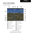
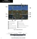
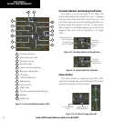
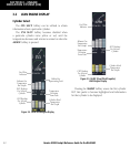
Figure 2-12 Horizontal Situation Indicator (360º)
8
14
9
6
5
4
3
2
1
7
13
12
11
10
Heading Bug
2
3
6
4
5
7
1
Turn Rate Indicator
Navigation Source
Course Deviation Indicator
TO/FROM Indicator
Course Pointer
Rotating Compass Rose
11
10
12
13
14
9
8
OBS Mode
Lateral Deviation Scale
Flight Phase
Aircraft Symbol
Lubber Line
Heading
Turn Rate and Heading Trend Vector
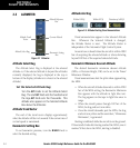
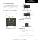
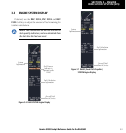
Turn Rate Indicator and Heading Trend Vector
Tick marks to the left and right of the lubber line
denote half-standard and standard turn rates. A magenta
turn rate trend vector shows the current turn rate. The
end of the trend vector gives the heading predicted in six
seconds, based on the present turn rate. At rates greater
than 4 deg/sec, an arrowhead appears at the end of the
magenta trend vector and the prediction is no longer
valid.
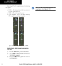
Figure 2-14 Standard-Rate Turn Indication
Turn Rate
Trend Vector
(standard rate)
Figure 2-13 Turn Rate Indicator and Trend Vector
Half-Standard Turn
Rate Tick Mark
Standard Turn
Rate Tick Mark
Turn Rate
Trend Vector
(rate > 4
deg/sec)
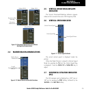
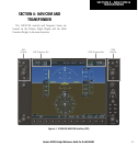
Course Pointer
The Course Pointer is a single line arrow (GPS, VOR1
and LOC1) or double line arrow (VOR2 and LOC2) which
points in the direction of the set course.
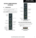
Lateral Deviation
Scale
Figure 2-15 Arc CDI and Compass Rose CDI
Course Deviation
TO/FROM Indicator