


Garmin G1000 Cockpit Reference Guide for the DA40/40F
2-5
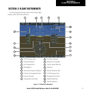
SECTION 2
FLIGHT INSTRUMENTS
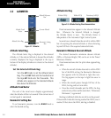
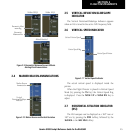
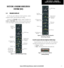
Within 100 ft
Altitude Reached
Within 2500 ft
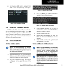
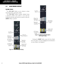
Figure 2-9 Barometric Minimum Descent Altitude
Alerting Visual Annunciations
Barometric
Minimum Box
Barometric Mini-
mum Bug
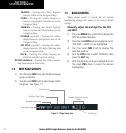
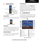
2.4 MARKER BEACON ANNUNCIATIONS
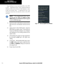
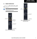
Figure 2-10 Marker Beacon and Vertical Deviation
Marker Beacon
Annunciation
Vertical
Deviation/Glideslope
Indicator
2.5 VERTICAL DEVIATION/GLIDESLOPE
INDICATOR
The Vertical Deviation/Glideslope Indicator appears
when an ILS is tuned in the active NAV frequency field.
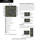
2.6 VERTICAL SPEED INDICATOR
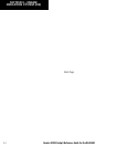
Figure 2-11 Vertical Speed Indicator
Vertical Speed Pointer
Vertical Speed Bug
Selected Vertical Speed
The actual vertical speed is displayed inside the
pointer.
When the Flight Director is placed in Vertical Speed
Mode (by pressing the VS Key) the Vertical Speed Bug
is displayed. Press the NOSE UP or NOSE DN Key to
adjust.
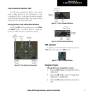
2.7 HORIZONTAL SITUATION INDICATOR
(HSI)
The HSI compass can be displayed as a 360° rose or
140° arc by pressing the PFD Softkey, followed by the
360 HSI or the ARC HSI Softkey.