


1-44
1.38 Adjusting Relative
Brilliance Levels of
Screen Data
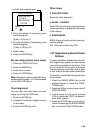
You can adjust relative brilliance levels of
various marks and alphanumeric readouts
displayed on the screen by following the
steps shown below:
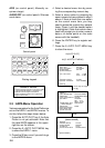
1. Press the RADAR MENU key on the
plotting keypad to show the FUNC-
TIONS menu.
2. Press the [9] key to show the BRIL-
LIANCE menu.
3. Select a desired menu item by press-
ing the corresponding numeric key. As
an example, press [4] if you want to
change the brilliance of echo trails.
4. Further press the same numeric key
as you pressed in step 3 above to se-
lect or highlight a desired brilliance
level.
5. Press the ENTER key to conclude your
selection followed by the RADAR
MENU key to close the FUNCTIONS
menu.
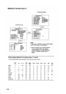
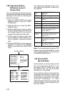
1 PULSEWIDTH
2 ECHO STRETCH
3 ECHO AVERAGE
4
5 ECHO COLOR
6 SHIP'S SPEED
7 INDEX LINES
8 2ND ECHO REJ
9 BRILLIANCE
0 [SYSTEM SETTING 1]
Hit [RADAR MENU].
1/2
OFF/1/2
OFF/1/2/3
YEL/GRN/COLOR*
LOG/NAV*/MAN
NO.2 VRM/MAN
OFF/ON
* R-type only
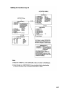
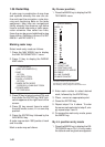
[FUNCTIONS]
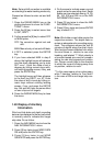
1 [FUNCTION]
2 CHAR
3 MARK
4 TRAIL
5 PANEL
6 +CURSOR
7 PLOT
8 HDG MARK
9 L/L GRID
0 CHART
[BRILLIANCE]
BRILL
BRILL
BRILL
DIMMER
BRILL
BRILL
BRILL
BRILL
BRILL
DIM/M1/M2/BRT
DIM/M1/M2/BRT
DIM/M1/M2/BRT
OFF/DIM/MBRT
OFF/DIM/MBRT
OFF/DIM/MBRT
DIM/M/BRT
DIM/M1/M2/BRT
DIM/M1/M2/BRT
Hit [9].
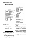
The table below describes which menu
item adjusts the brilliance of which pic-
ture element.
Menu
item
Of which brilliance is
adjusted?
CHAR Alphanumeric readouts
MARKS Bearing scale, EBLs and
VRMs
TRAILS Echo trails
PANEL Operator control panel
+CURSOR Trackball cursor (+)
PLOT Plot symbols and marks for
E-plot and optional Auto
Plotter ARP-25
HDG
MARK
Heading line and stern marker
(Stern marker displayed on
R-type only.)
L/L GRID Lat/long grid lines generated
by optional Auto Plotter
ARP-25
CHART Chart generated by optional
Auto Plotter ARP-25
Note: You should adjust the entire CRT
brilliance by operating the BRILL control
before adjusting relative brilliance levels
on the BRILLIANCE menu.
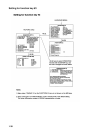
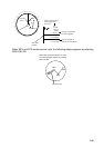
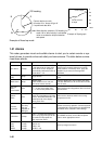
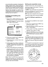
1.39 Set and Drift
(Set and Rate)
Set the direction in which a water current
flos, can be manually entered in 0.1 - de-
gree steps. Drift, in another word Rate,
the speed of tide, can also be entered
manually in 0.1 knot steps.
Set and drift corrections are benefcal for
increasing the accuracy of vectors and
target data. The correction is best made
in the head-up mode with true vector,
watching landmasses, or other
stationarytargets. If they have vectors, set
and drift values should be adjusted until
they lose vectors.