


1-26
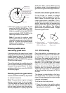
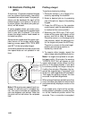
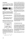
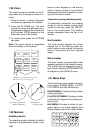
Trail gradation
Echo trails may be shown in monotone
or gradual shading. Gradual shading
paints the trails getting thinner with time
just like the afterglow on an analog PPI
radar.
Monotone
(Single)
Gradual shading
(Multi)
Selection of monochrome or gradual
shading requires almost the same opera-
tion as for true or relative trails setup pro-
cedure described above except that you
should:
- Press the [7] key to select menu
item 7 TRAIL GRAD (graduation) in
step 4.
- Press the [7] key to select (or high-
light) SGL (single tone) or MULT
(multiple shading) option in step 5.
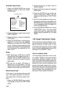
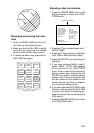
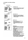
Displaying and erasing echo trails
Press the ECHO TRAILS key to activate
or deactivate the echo trails feature.
HL
OFF
ECHO
TRAILS
MODE
ORIGIN
MARK
VECTOR
TRUE/
REL
VECTOR
TIME
GUARD
ALARM
EBL
OFFSET
OFF
CENTER
Each press of the ECHO TRAILS key
within 5 seconds cyclically changes echo
trail length (time) to 30 seconds, 1, 3, 6,
15 and 30 minutes, continuous echo trail-
ing and OFF. The current echo trail set-
ting is displayed at the lower-right corner
of the screen.
OFF → 30 sec → 1 min → 3 min → 6 min
Continuous ← 30 min ← 15 min ↵
↵
Suppose that "3 MIN" has just been se-
lected. If the ECHO TRAILS key is hit
more than 5 seconds later, echo trails are
removed from the display (memory still
alive with echo trail timer count going on).
Next hitting of the key calls out the echo
trails on the screen. To proceed to longer
plot intervals, successively push the
ECHO TRAILS key with a hit-and-release
action. The larger the echo trail length,
the larger the echo trail plot interval.
Note: Holding the ECHO TRAILS key de-
pressed for about 3 seconds will cause a
loss of echo trail data so far stored in an
in memory.
Resetting echo trails
To reset (or clear) the echo trail memory,
hold the ECHO TRAILS key depressed
for about 3 seconds. Echo trails are
cleared and the trailing process restarts
from time count zero at current echo trail
plot interval. When memory assigned to
echo trailing becomes the echo trail timer
at the lower-right corner of the screen
freezes and the oldest trails are erased
to show the latest trails.
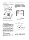
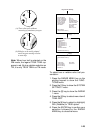
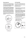
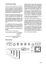
1.26 Parallel Index Lines
Parallel index lines are useful for keeping
a constant distance between own ship
and a coastline or a partner ship when
navigating. Index lines are drawn in par-
allel with the No.2 EBL (No.2 EBL must
be active). The orientation of the index
lines is controlled with the EBL control and
the intervals between the lines adjusted
with the VRM rotary control (provided that
No.2 VRM is active).
Maximum number of the index line can
be set the Initial Setting menu: 2, 3 or 6.