1-16
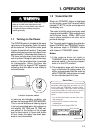
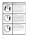
Note: For stable reception of certain types
of radar beacons (racons) or SART
(Search and Rescue Radar Transponder)
as required by SOLAS 1974 as amended
1988 (GMDSS), it is recommended to turn
the interference rejector off.
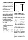
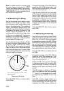
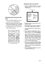
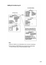
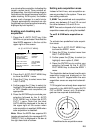
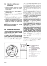
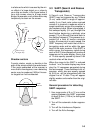
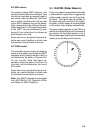
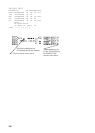
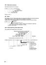
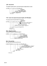
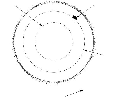
1.16 Measuring the Range
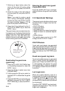
Use the fixed range rings to obtain a rough
estimate of the range to a target. They
are concentric solid circles about own
ship, or the sweep origin. The number of
rings is automatically determined by the
selected range scale and their interval is
displayed at the upper-left position of the
screen. Press the RINGS key on the
mode panel to show the fixed range rings
if they are not displayed. Successive
presses of the RINGS key gradually in-
crease their brightness in 4 steps and fifth
press erases the range rings.
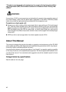
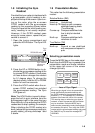
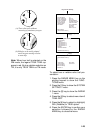
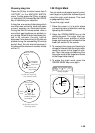
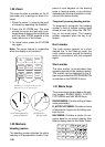
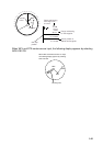
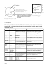
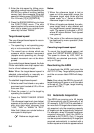
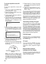
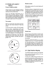
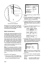
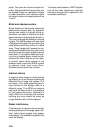
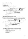
Use the Variable Range Markers (VRMs)
for more accurate measurement of the
range to a target. There are two VRMs,
No.1 and No.2, which appear as dashed
rings so that you can discriminate them
from the fixed range rings. The two VRMs
can be distinguished from each other by
different lengths of dashes.
000
010
020
030
040
050
060
070
080
090
100
110
120
130
140
150
160
170
180
190
200
210
220
230
240
250
260
270
280
290
300
310
320
330
340
350
No.1
VRM
Target
blip
No.2
VRM
VRM
>0.665NM<
1.186NM
Active VRM is identified
with this marker.
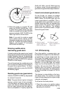
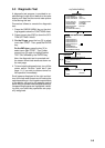
Measuring the range
Press the VRM ON key to display either
of the VRMs.
Successive presses of the VRM ON key
toggle the active VRM between No.1 and
No.2 and the currently active VRM read-
out is circumscribed by >.....<.
Align the active VRM with the inner edge
of the target of interest and read its dis-
tance at the lower-right corner of the
screen. Each VRM remains at the same
geographical distance when you operate
the RANGE+ or RANGE- key. This means
that the apparent radius of the VRM ring
changes in proportion to the selected
range scale.
Press the VRM OFF key to key to erase
each VRM.
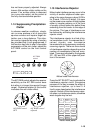
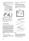
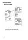
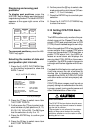
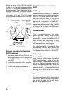
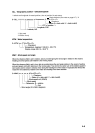
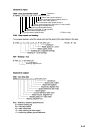
1.17 Measuring the Bearing
Use the Electronic Bearing Lines (EBLs)
to take bearings of a target. There are two
EBLs, No.1 and No.2, which are toggled
by successive presses of the EBL ON key.
Each EBL is a straight dashed line extend-
ing out from the own ship position up to
the circumference of the radar picture.
The fine dashed line is the No.1 EBL and
the coarse dashed one is the No.2 EBL.
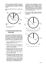
Press the EBL ON key to display either of
the EBLs.
Successive presses of the EBL ON key
toggle the active EBL between No.1 and
No.2 and the currently active EBL read-
out is circumscribed by >...<.
Rotate the EBL rotary control clockwise
or counterclockwise until the active EBL
bisects the target of interest, and read its
bearing at the lower-left corner of the
screen.
The EBL readout is affixed by "R" (rela-
tive) if it is relative to own ship's heading,
"T" (true) if it is referenced to the north,
as determined by RADAR 2 menu set-
tings.
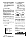
Each EBL carries a range marker, or a
short line crossing the EBL at right angles
and its distance from the EBL origin is in-
dicated at the VRM readout whether or