1
Reference Manual
00809-1600-4530, Rev AA
Section 1: Introduction
March 2015
Introduction
Section 1 Introduction
1.1 Manual overview
This manual provides commissioning, verification, and validation information for the
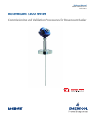
Rosemount 5300 Series Radar Transmitters.
This manual is intended to be used with the Rosemount 5300 Series Reference Manual
(document number 00809-0100-4530).
1.2 Tools
The following tools and documents are recommended to use during the installation and
commissioning procedures:
Field Communicator 475/laptop with Rosemount Radar Master (RRM) or AMS
®
Device
Manager
HART
®
modem/FOUNDATION
™
fieldbus modem
Multimeter
Screw driver, Phillips 2 mm or flat head 6 mm (for wire terminals)
Screw driver, flat head 8 mm (for external ground screw)
Adjustable spanner (for cable glands)
Wrench, 54 mm (to install or remove the transmitter head)
Allen key, 3 mm, 4 mm, and 5 mm (to loose and fix the weight)
Allen key, 2 mm (to secure the coaxial probe)
Hack saw (to shorten the rigid probes)
Heavy duty nipper (to shorten the flexible probes)
1.3 Documents
Rosemount 5300 Series Superior Performance Guided Wave Radar Level and Interface
Transmitter Quick Installation Guide
(document number 00825-0100-4530)
Rosemount 5300 Series Superior Performance Guided Wave Radar Reference Manual
(document number 00809-0100-4530)
Rosemount 5300 Series - Using Guided Waver Radar for Level in High Pressure Steam
Applications Technical Note
(document number 00840-0100-4530)


