6
Reference Manual
00809-1600-4530, Rev AA
Section 2: Installation & configuration
March 2015
Installation and Configuration
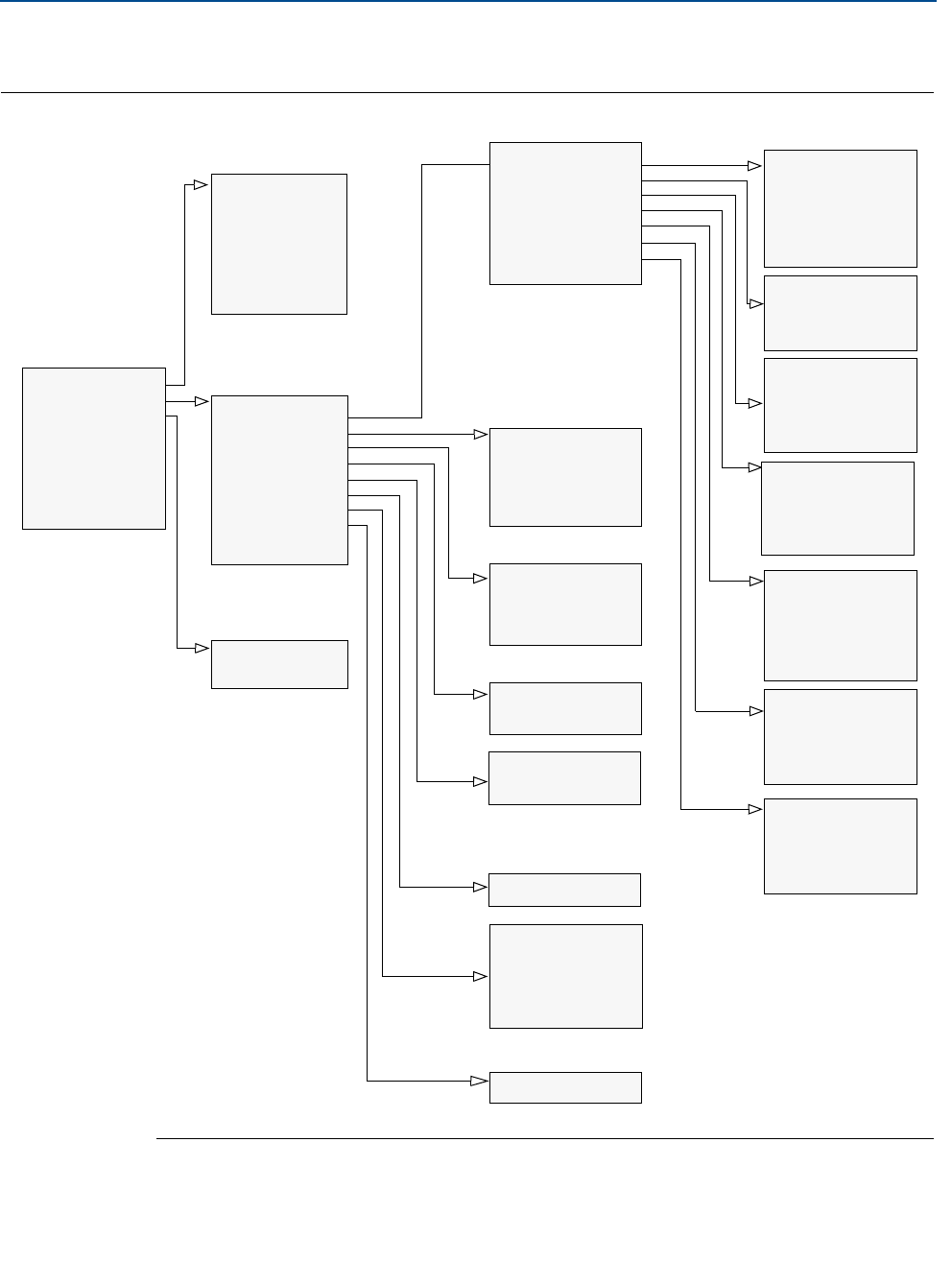
2.2.3 Basic configuration using a Field Communicator
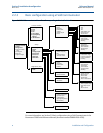
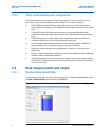
Figure 2-3. Field Communicator Menu Tree Corresponding to Device Revision 3
For more information, see Section 5.5 Basic configuration using a Field Communicator in the
Rosemount 5300 Series Reference Manual (document number 00809-0100-4530).
Process variables
1 Process variables
2Setup
3Diagnostics
4 Primary variable
Value
5Analog out
6Distance
7 Signal strength
1Primary variable
22nd
33rd
44th
5 All variables
6 Signal Quality
Metrics
7 Identification
1Basic setup
2Device
3Tank
4Analog output
5 Echo tuning
6Echo curve
7Advanced
8Calibration
1 Diagnostics
2Tools
1Variable mapping
2Probe
3Geometry
4Environment
5Volume
6Analog output
7Finish
1 Identification
2Variable mapping
3LCD
4 Communication
5Alarm/sat. limits
1Probe
2Geometry
3Environment
4Volume
1Analog out
2 Alarm/sat. limits
1 Echo peaks
2Thresholds
1 Echo curve
1Near zone
2 Probe End Projection
3Dynamic Vapor
Compensation
4 Signal Quality Metrics
5 Echo tracking
Setup
Diagnostics/Tools
1 Primary variable
22nd
33rd
44th
5HART digital units
6Damping value
7Device status
1 Probe type
2Probe length
3 Upper Null Zone
4Drawing
1 Tank height
2 Mounting type
3 Inner diameter
4 Nozzle height
5Drawing
1Measurement mode
2 Product diel. range
3 Upper prod. dielectr.
4 Process conditions
5Drawing
1 Calculation method
2 Tank diameter
3Tank length
4Volume offset
5 Strapping table
6Drawing
1Primary variable
2Range values
3Alarm mode
4Sensor limits
5Alarm mode definit.
1Finish setup
2 Device specific setup
3 After setup restart
F/W
4Restart device
1Analog output


