


11
Reference Manual
00809-1600-4530, Rev AA
Section 2: Installation & configuration
March 2015
Installation and Configuration
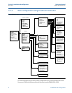
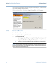
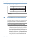
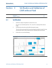
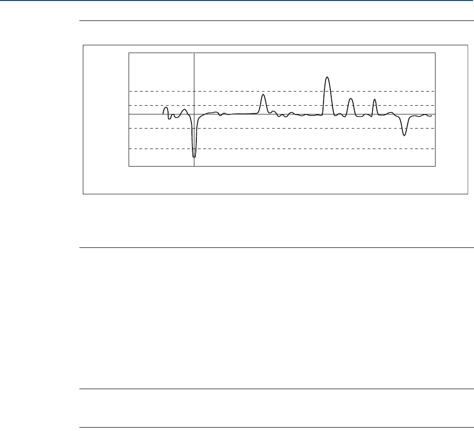
Figure 2-8. The Echo Curve Presents All Visible Echoes
2.5 Common problems and recommended actions
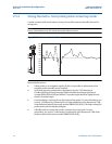
2.5.1 Double bounce
Tall, narrow, and/or rough nozzles may create double bounces, which disturb the measurement
signal. The double bounce always appears at twice the disturbance distance. For example, the
end of the nozzle may create a peak at 10 in. (254 mm). A second peak will appear at 20 in.
(500 mm).
Note
Trim Near Zone should not be completed when the unit is installed in an empty metal tank. A
small amount of fluid should be added before the Trim Near Zone step is completed.
Recommended actions:
Verify that mounting considerations are followed, as described in Section 3.2 Mounting
Considerations in the Rosemount 5300 Series Reference Manual (document number
00809-0100-4530).
Perform Trim Near Zone. See Appendix C.3.1 Use the Trim Near Zone Function in the
Rosemount 5300 Series Reference Manual (document number 00809-0100-4530) for
activation details. Fine-tune performance by trimming echoes in the near zone.
Adjust Upper Null Zone (UNZ). See Appendix C.3.2 Changing the Hold Off
Distance/Upper Null Zone in the Rosemount 5300 Series Reference Manual (document
number 00809-0100-4530) for details. Exclude any echo “before” the UNZ.
Adjust Surface Threshold (ATC). See Appendix C.4 Threshold Settings in the Rosemount
5300 Series Reference Manual (document number 00809-0100-4530) for details.
Exclude any echo weaker than the threshold.
A
B
C
D
2000
1500
1000
0
-1000
-1500
- 1.0
0
1.0
2.0 3.0 4.0 5.0 6.0
Amplitude, mV
Distance, m
A. Interface threshold
B. Surface threshold (ATC)
C. Probe end threshold
D. Reference threshold