47
Reference Manual
00809-1600-4530, Rev AA
Appendix A: Commissioning Checklist
March 2015
Commissioning Checklist
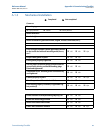
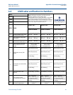
A.4 GWR radar verification in chambers
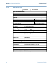
UNIT:
Note: Verification procedure is performed under
ambient conditions. For dynamic vapor
compensations units, ensure that the DC is calculated
at 1.0 before starting verification process. If static
vapor compensation is used, set vapor DC to 1 for the
test and reset to desired value when finished. For all
other units, vapor DC should be set at 1.
DATE:
TIME:
TECH:
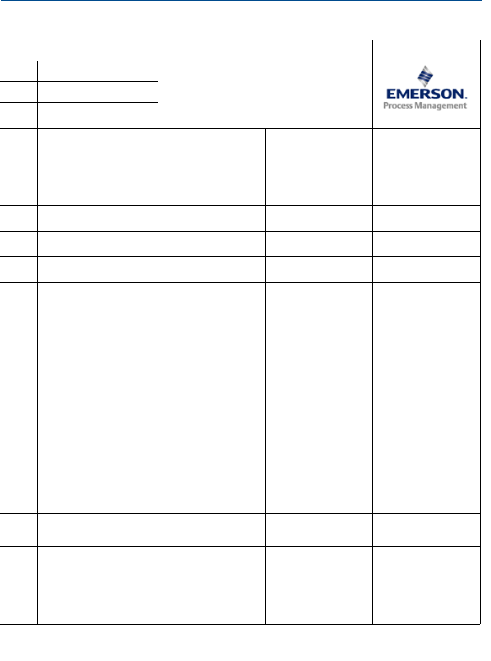
STEP TASK
DEVICE TAG:
__________________
DEVICE TAG:
__________________
DEVICE TAG:
__________________
SERIAL NUMBER:
__________________
SERIAL NUMBER:
__________________
SERIAL NUMBER:
__________________
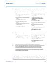
1
Isolate chamber using upper
and lower block valves
YES NO YES NO YES NO
2
Vent chamber using upper
vent valves
YES NO YES NO YES NO
3
Open bottom vent valves
and connect water source
YES NO YES NO YES NO
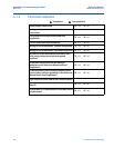
4
Open up echo curve and
start continuous record
mode
**Leave in continuous
record mode
throughout test**
**Leave in continuous
record mode
throughout test**
**Leave in continuous
record mode
throughout test**
5
Verification at zero (LRV -
4mA)
Radar Output (Level):
____________________
Radar Output (mA):
__________________
DCS Reading:
__________________
Radar Output (Level):
____________________
Radar Output (mA):
__________________
DCS Reading:
__________________
Radar Output (Level):
____________________
Radar Output (mA):
__________________
DCS Reading:
__________________
6
Verification at nominal level
condition
Radar Output (Level):
____________________
Radar Output (mA):
__________________
DCS Reading:
__________________
Radar Output (Level):
____________________
Radar Output (mA):
__________________
DCS Reading:
__________________
Radar Output (Level):
____________________
Radar Output (mA):
____________________
DCS Reading:
____________________
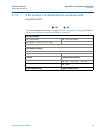
7
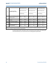
DCS (zero check - bias
added)
DCS Reading - (w/ Bias):
____________________
DCS Reading - (w/ Bias):
____________________
DCS Reading - (w/ Bias):
____________________
8
Trim gauges to read
identical levels (if needed)
Enter “Calibration
Offset” values in gauges
as required to bring
them all to identical level
readings
Enter “Calibration
Offset” values in gauges
as required to bring
them all to identical level
readings
Enter “Calibration
Offset” values in gauges
as required to bring
them all to identical level
readings
9
View echo curve and make
threshold adjustments
**Adjust only if
needed**
**Adjust only if
needed**
**Adjust only if
needed**


