


36
Reference Manual
00809-1600-4530, Rev AA
Section 6: SIS Installations
March 2015
SIS Installations
6.2 Configuring in SIS applications
Use a HART
®
compliant master, such as Rosemount Radar Master (RRM) or a Field
Communicator, to communicate with and verify configuration of the Rosemount 5300 Series.
These instructions are applicable to the Rosemount 5300 Series safety-certified options with
any differences noted.
Damping
User-adjusted damping will affect the transmitter’s ability to respond to process changes.
Therefore, the damping values + response time should not exceed the loop requirements.
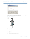
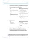
Alarm and saturation levels
DCS or safety logic solver should be configured to handle both High alarm and Low alarm. It is
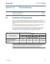
also required that the transmitter is configured for High or Low alarm. Figure 6-1 identifies the
alarm levels available and their operation values
(1)
.
Figure 6-1. Alarm Levels and Operation Values
It is assumed that the current output signal is fed to a SIL 2-compliant analog input board of a
safety logic solver.
Note
Only the High or Low Alarm Mode can be used for the safety function. Do not choose Freeze
Current.
Write protection
A Rosemount 5300 Series safety-certified transmitter should always be protected from
unintentional configuration changes by a password protected function.
(1) In certain cases, the transmitter does not go into the user defined alarm state. For example, in case of a short circuit, the transmitter goes into High Alarm state even
if Low Alarm has been configured.
Rosemount Alarm Level
Normal Operation
3.75 mA
(1)
(1) Transmitter failure, hardware or software alarm in Low position.
4 mA 20 mA 21.75 mA
(2)
3.9 mA
Low Saturation
20.8 mA
High Saturation
Namur Alarm Level
Normal Operation
3.6 mA
(1)
4 mA 20 mA 22.5 mA
(2)
(2) Transmitter failure, hardware or software alarm in High position.
3.8 mA
Low Saturation
20.5 mA
High Saturation