


Register-Based Programming 87Appendix B
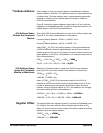
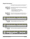
Reading the
Status/Control Register
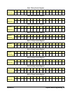
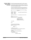
For Status/Control register reads, three bits are defined as follows.
• MODID (bit 14): 0 indicates the module has been selected by
MODID (module ID) and a 1 indicates the module has not been
selected. For example, if an E1466A matrix module is not busy
(bit 7 = 1) and the interrupt is enabled (bit 6 = 0), a read of the
Status/Control Register (base + 04
16
) returns DBBF.
• Module ID (bits 10 - 13): The following bit representations determine
the module configuration (E1465A/66A/67A determined by the
terminal module attached).
• Busy (bit 7): 0 indicates the module is busy. Each relay requires
about 7 ms execution time during which time the matrix module
is busy. Bit 7 of this register is used to inform the user of a busy
condition.
• Enable (bit 6): 0 indicates the interrupt is enabled. The interrupt
generated after a channel has been closed can be disabled. Bit 6
of this register is used to inform the user of the interrupt status.
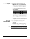
Writing to the
Status/Control Register
You can only write to bits 0 and 6 of the Status/Control Register.
• Enable (bit 6): Writing a "1" to this bit disables the interrupt function
of the module.
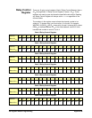
• Soft Reset (bit 0): Writing a "1" to this bit does not soft reset the
module. To reset each relay in register-based programming, you
must write all 0s to all 16 banks to open all relays.
NOTE When writing to the registers it is necessary to write "0" to bit 0 after the
reset has been performed before any other commands can be programmed
and executed. SCPI commands take care of this automatically.
Model/Bits (13) (12) (11) (10)
E1465A 1 0 0 1
E1466A 0 1 1 0
E1467A 0 1 0 1