


Using the Matrix Modules 47Chapter 3
Understanding Matrix Modules
This section provides internal configuration details about the E1465,
E1466A, and E1467A matrix modules, including advantages of latching
relays and module operation.
Advantages of
Latching Relays
There are several advantages to using the E1465A/E1466A/E1467A
latching relays, as follows. The main disadvantage of latching relays is
that the relay state is unchanged at power-on, power-off, or following a reset.
Therefore, the device's firmware must ensure that all relays are open
following these conditions.
• With 256 relays on the dense matrix relay module, latching relays
prevent excessive current being drawn from the power supply if
the user closes too many relays accidentally. Energy is saved
since power is not continually applied to keep a latching relay
closed.
• By not continually applying power, the relay coil does not heat up.
This is important because the two metal contacts inside the relay,
in effect, form a thermocouple. Thus, temperature differences on
the relay contacts cause thermal EMF (electromotive force) to be
generated.
• The life of a latching relay is usually longer than that of a
nonlatching relay because of the power that must be continually
applied to close a nonlatching relay.
• In conventional switch module designs, the module interrupts the
central processing unit (CPU) each time a relay is opened or
closed. For the E1465A/E1466A/E1467A matrix relay modules,
the CPU is interrupted one time after all relays in the specified
channel list have been opened or closed. Thus, system
throughput speed is increased.
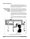
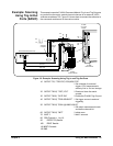
Matrix Module
Operations
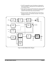
The following paragraphs describe matrix module operations (see Figure
3-3).
• A command is sent to the matrix module and is stored in FIFO
memory.
• Once the data is in memory, the VME Timing PAL (programmable
array logic) asserts DTACK*. This signals the CPU on the matrix
module's commander that it is now free to service other tasks.
• The VME Timing PAL signals the FIFO Interface PAL to execute
the command. During execution, the Data Bus FIFO EMPTY*
flag signals the FIFO Interface PAL to read the Data Bus and
Address Bus FIFO and generate 7 msec pulses to activate the
relays. Only one 7 msec pulse is required per relay bank (up to
16 relays).