


36 Using the Matrix Modules Chapter 3
Power-on and Reset Conditions
The matrix modules use latching relays and the relay state remains
unchanged during power-up and power-down. However, if an E1406A
Command Module is used, the firmware opens all relays during power-up
and a when *RST (reset) is executed. See Table 3-2 for default values.
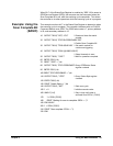
Matrix Modules Identification
The following programs use the *RST, *CLS, *IDN?, CTYP?, and CDES?
commands to reset and identify the matrix modules. For example, a typical
printout for the E1465A 16x16 matrix module will be similar to:
HEWLETT-PACKARD,SWITCHBOX,0,A.04.00
16 x 16 Matrix Switch
HEWLETT-PACKARD,E1465A,0,A.04.00
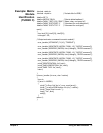
Example: Matrix
Module
Identification
(BASIC)
10 DIM A$[50], B$[50], C$[50]
I Dimensions three string
variables to fifty characters
20 OUTPUT 70915;"*RST; *CLS"
! Outputs the commands to reset
and clears the status register
30 OUTPUT 70915; "*IDN?"
! Queries for module identification
40 ENTER 70915; A$
I Enters the results into A$
50 OUTPUT 70915; "SYST:CDES? 1"
! Outputs the command for a card
description
60 ENTER 70915; B$
! Enters the results into B$
70 OUTPUT 70915; "SYST:CTYP? 1"
! Outputs the command for the
card type
80 ENTER 70915; C$
! Enters the results into C$
90 PRINT A$, B$, C$
! Prints the contents of variables
A$, B$, and C$
100 END
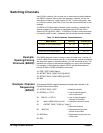
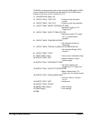
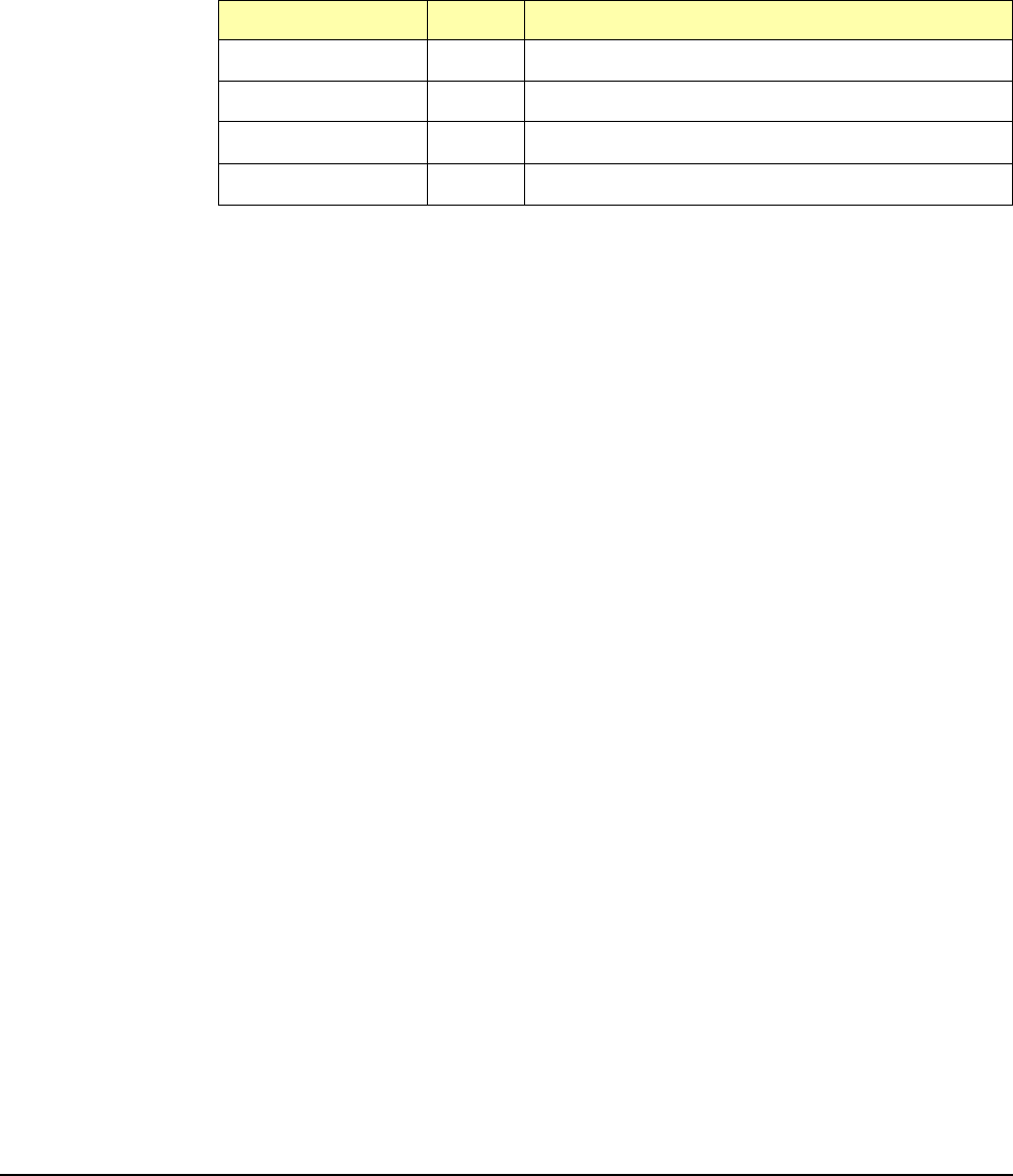
Table 3-2. *RST (Reset) Default Conditions
Parameter Default Description
ARM:COUNt
1
Number of scanning cycles is 1
TRIGger:SOURce IMM Will advance scanning cycles automatically
INITiate:CONTinuous
OFF
Number of scanning cycles is set by ARM:COUNt
OUTPut[:STATe]
OFF
Trigger output from EXT or TTL sources is disabled