


Configuring the Matrix Modules 21Chapter 2
Setting the Logical
Address Switch
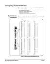
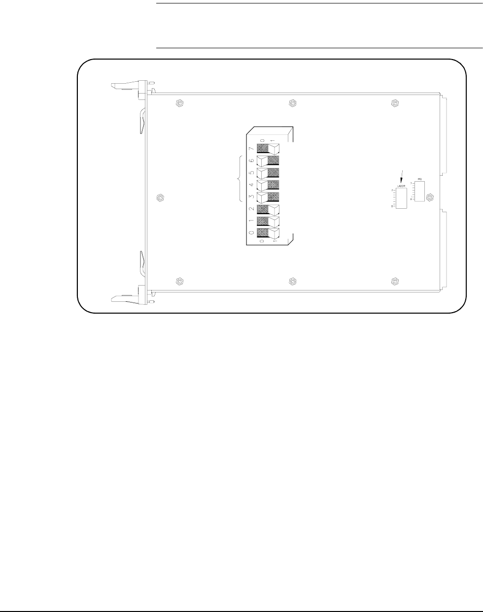
The logical address switch (LADDR) factory setting is 120. Valid address
values are from 1 to 255. The matrix module can be configured as a single
instrument or as a switchbox. See Figure 2-2 for switch position information.
NOTE The address switch selected value must be a multiple of 8 if the module is
the first module in a switchbox used with a VXIbus command module and
is being instructed by SCPI commands.
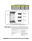
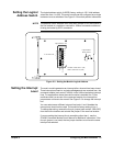
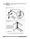
Setting the Interrupt
Level
The matrix module generates an interrupt after a channel has been closed.
These interrupts are sent to, and acknowledgements are received from, the
command module (such as an E1406A) via the VXIbus backplane interrupt
lines. For applications where the matrix module is installed in a C-Size
mainframe and is a servant of the command module, the interrupt line
jumper does not have to be moved. See Figure 2-3 to change the interrupt
line.
You can select seven different interrupt line levels. Line X disables the
interrupt and should not be used. The module's factory setting is line 1.
To change the setting, remove the four-pin jumper (part number 1258-0247)
from the old line location and reinstall the jumper in the new line location.
If you are setting the interrupt line to something other than 1, see the
E1406A Command Module User's Manual for additional information. If the
four-pin jumper is not used, the two jumper locations must have the same
interrupt line selected.
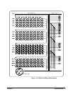
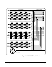
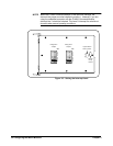
Figure 2-2. Setting the Module Logical Address
8+16+32+64=120
Logical Address = 120
Logical Address
Switch Location
128
64
32
16
8
4
2
1
C
L
O
S
E
D
O
P
E
N
CLOSED = Switch Set To 1 (ON)
OPEN = Switch Set To 0 (OFF)