


Using the Matrix Modules 41Chapter 3
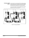
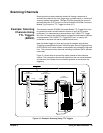
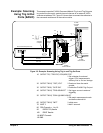
Example: Scanning
Using Trig In/Out
Ports (BASIC)
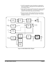
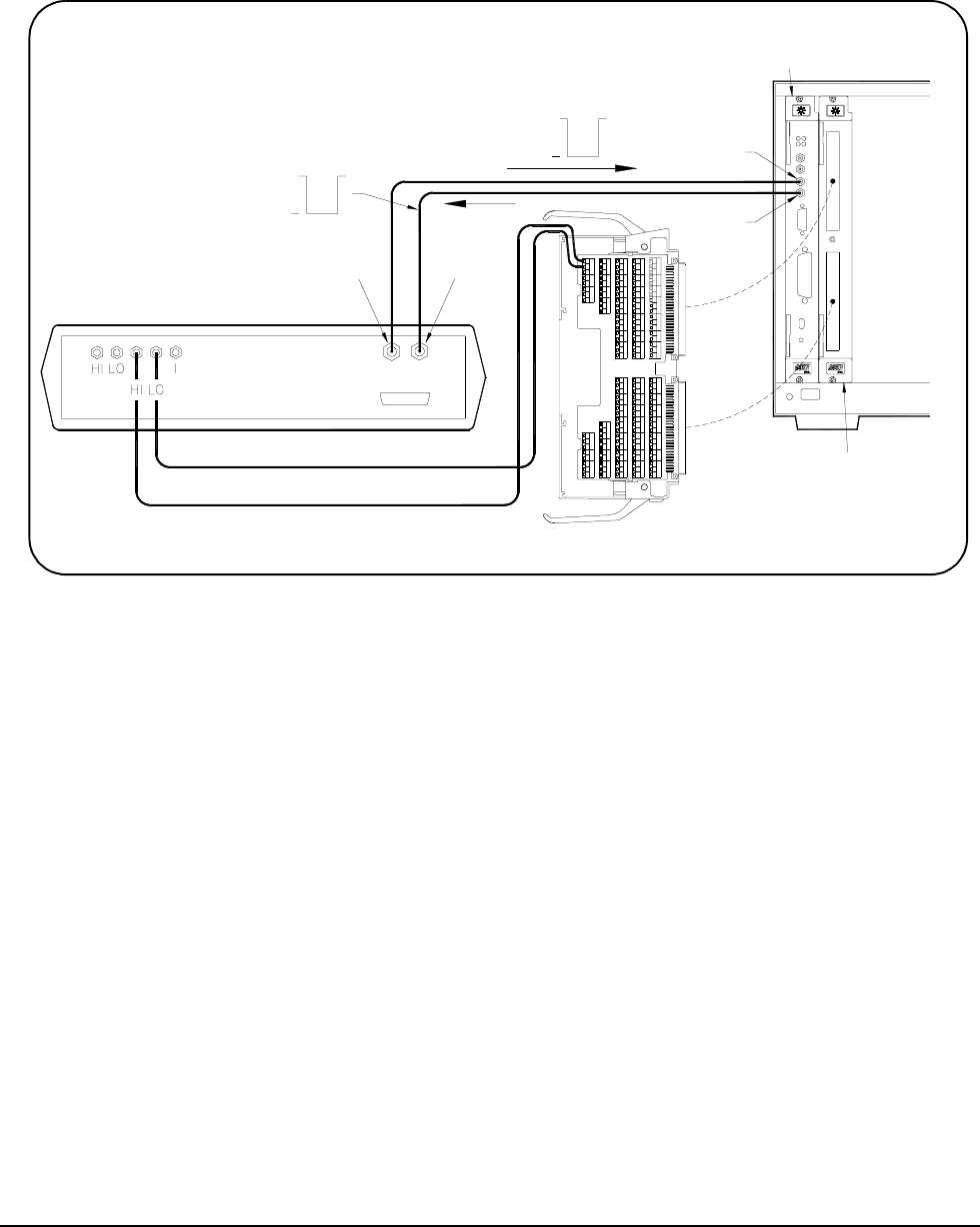
This example uses the E1406A Command Module Trig In and Trig Out ports
to synchronize the matrix module channel closures to an external 3457A
voltmeter at address 722. Figure 3-2 shows how to connect the voltmeter to
the command module and to the matrix module.
10 OUTPUT 722; "TRIG EXT; DCV;MEM FIFO"
! Set voltmeter for external
trigger, DCV measurements,
memory first in, first out storage
20 OUTPUT 70915; "*RST;*CLS"
! Reset and clear the matrix
module
30 OUTPUT 70915; "OUTP ON"
! Enable the E1406A Trig Out port
40 OUTPUT 70915; "TRIG:SOUR:EXT"
! Set trigger source to external
triggering
50 OUTPUT 70915; "SCAN (@10000:10015)"
! Set matrix measurement mode
and define channel list
60 OUTPUT 70915; "INIT"
! Initiate scan
70 WAIT 2
! Wait 2 seconds
80 FOR Channels = 1 to 16
90 ENTER 722;Results
100 PRINT Results
110 NEXT Channels
120 END
Figure 3-2. Example: Scanning Using Trig In and Trig Out Ports
Trig
Trig
In
Out
E1406A
Command
Module
Complete
3457A Multimeter (Rear View)
Trigger
E1466A
Matrix Module
Voltmeter External
+5V
0V
0V
+5V
Row 00L
Row 00H
E1466A
Terminal Module