


Chapter 5: Installation 5-9
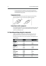
The dc power and NMEA inputs/outputs should be connected to the
POWER/NMEA connector at the rear of the RayChart 420. The connector pin
functions are detailed in the following table.
FunctionFunction
FunctionFunction
Function
ColorColor
ColorColor
Color
Battery negative Black
Battery positive (10.0Vdc to 18.0Vdc) Red
NMEA data input (+ve) White
NMEA input (-ve) - common Green
Not connected Grey
NMEA data out Yellow
Data output common Brown
Not connected Screen
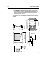
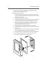
Connect the power supply using the standard power cable supplied, as follows:
1. Connect the moulded power plug to the POWER/NMEA connector on the
rear of the chartplotter. Run the free end back to the vessel’s distribution
panel or, if insufficient cable length to a junction box.
2. Cut the cable to length and connect the red wire, via a fuse, to the +ve
battery terminal and the black wire to 0V (-ve battery terminal). Protect the
circuit with a 1A quick blow fuse or circuit breaker.
3. Use a suitable junction box to connect to NMEA equipment if required.
4. Cut any unused cores short or insulate and tape back.
Note: If the power connections are accidentally reversed, the system will not
function. Use a volt meter to check that the input power leads are connected
with the correct polarity.
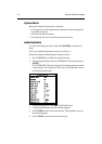
5.7 System Check and Initial Switch On
When you have installed your Chartplotter and made all the connections, you
need to check your installation before using the system for navigation. If you
encounter any problems, refer to Chapter 6, Maintenance and Fault Finding.
EMC Conformance
Always check the installation before going to sea to make sure that it is not
affected by radio transmissions, engine starting etc.