


Chapter 5: Installation 5-7
5.6 Cabling
Introduction
The following points need to be considered before installing the system cables:
• The minimum requirements are a power cable and a connection from the
associated GPS. Additional cables will be required if you are connecting to
other equipment.
• All cables should be adequately cleated and protected from physical
damage and exposure to heat. Avoid running cables through bilges or
doorways, or close to moving or hot objects.
• Where a cable passes through an exposed bulkhead or deckhead, a
watertight gland or swan neck tube should be provided.
You need to run the following cables:
• POWER/NMEA cable, supplied with the unit. This has a connector at one
end for connecting to the unit and seven cores at the other for connecting the
power supply and (optionally) NMEA.
• GPS cable from the associated GPS antenna with a connector at one end.
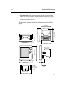
Chartplotter connectors
The following connectors are provided at the rear of the chartplotter:
• GPS, for connection to the associated GPS receiver.
• POWER/NMEA, for 12Vdc power connection and NMEA inputs/outputs.
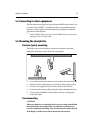
GPS connector
The GPS connector provides power and data connections to the associated
GPS (RC420) or dGPS (RC420D).
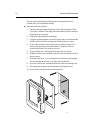
Connect the GPS/dGPS using the attached cable, as follows:
1. Mount the GPS/dGPS according to its accompanying Installation Guide.
2. Feed the cable through to the rear of the chartplotter.
3. Coil up any unused cable in an appropriate safe space out of view. Do not
bend the cable tighter than 100mm (4in) radius.
Note: If the supplied cable is too short, use an extension cable (Part# E35003)
available from your local Raytheon dealer.
Connections to the GPS connector on the rear of the display unit are detailed in
the following table: