


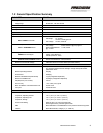

1.2 General Specification Summary
PARAMETER VALUE
Power Input
Voltage Range 80-160 VDC; 120 VDC nominal
Maximum Current 20 A
Typical Transient Current +20A < 60ms; +10A < 120ms; -5A < 100ms
Typical Continuous Current < 1A
Inputs and Outputs
Discrete Inputs
RUN and RESET commands
ON Voltage:
12 – 32 VDC,
+24 VDC nominal @ 6.5 mA
OFF Voltage:
1.0 VDC, maximum
Discrete Outputs
FAULT & OVERTEMP alarms
OFF Voltage:
32 VDC maximum @ 150 µA typical
Effective ON Resistance
1.1 kΏ, nominal
@ ≥ 1.5 VDC:
Analog Input
DEMAND command signal
Current: 4 to 20 mA; 25 mA Maximum
Voltage: 5 VDC Maximum
Internal Impedance: 200 Ώ
Analog Outputs
POSITION & MTR CURRENT feedback
Current: 4 to 20 mA
External Load Resistance: 300 Ώ, Maximum
Maximum Common Mode Voltage ±200 VDC User I/O to 120 VDC Return (less serial interface)
Performance All performance values are based on use with HFG2.0 in default configuration.
Any changes to HFG2.0 firmware settings to change stroke profile will alter
performance values.
Maximum Operating Pressure 500 psig
Proof Pressure 2000 psig
Minimum Controllable Flow (Natural Gas) 15 pph (configuration dependent)
Maximum Controllable Flow 30,000 pph (configuration dependent)
Step Response (10% to 90%) 100 ms
Flow Accuracy
± 5% of flow point, typical
Mean Time Before Unscheduled Removal 30,000 Hours
Life Cycles 32,000 Minimum
Environmental
Temperature, Operating Ambient:
-40° C (-40° F) to +93° C (+200° F)
Temperature, Operating Fuel:
-40° C (-40° F) to +125° C (+257° F)
Temperature, Storage
-40° C (-40° F) to +125° C (+257° F)
Environmental Rating Rated to CSA Type 3 and European IP65
Sealed against dust, protected against water
EMC Meets EN 50081-2 and EN50082-2 for DC powered industrial equipment
Vibration Meets Mil-Std-810E, Category 4 (5 – 2000 Hz)
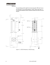
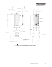
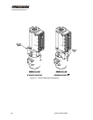
INSTALLING THE HFG2.0 3