


30 HFG2.0 USER GUIDE
Note: The MCE analog and discrete signal interfaces are
electrically isolated. The serial communication interface is
optically isolated
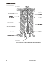
2.3 Mechanical Description
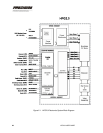
The HFG2.0 consists of two main parts, an actuator and a valve
assembly.
Actuator
The actuator is the primary drive mechanism for the valve assembly. The
actuator portion of the HFG2.0 consists of four main assemblies:
• Main Housing Assembly
• Brushless DC Motor Assembly
• Resolver Assembly
• Linear Drive Mechanism
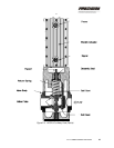
Main Housing Assembly
The main housing assembly consists of the main housing, motor cover,
extension-rod bearing, and associated seals. The main housing assembly
is the primary structural system component and supports all the bearings,
motor cover, mountings, and connectors. It also provides explosion-proof
containment.
The housing is fitted with a stainless steel liner to provide thermal and
dimensional stability for the main bearing. This liner is permanently
installed into the aluminum main housing. A retaining ring is included for
redundant retention.
The main housing also contains rigid mechanical stops to prevent
extension rod travel beyond the design specification. See Figure 2-2.
Brushless DC Motor Assembly
A brushless DC motor powers the HFG2.0 linear drive mechanism. The
DC motor consists of a stator and rotor. See Figure 2-2.
Motor Stator
The motor stator is attached to the main housing by a pre-loaded wave
spring and screws. Thermistors are embedded in the stator windings to