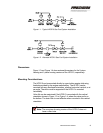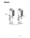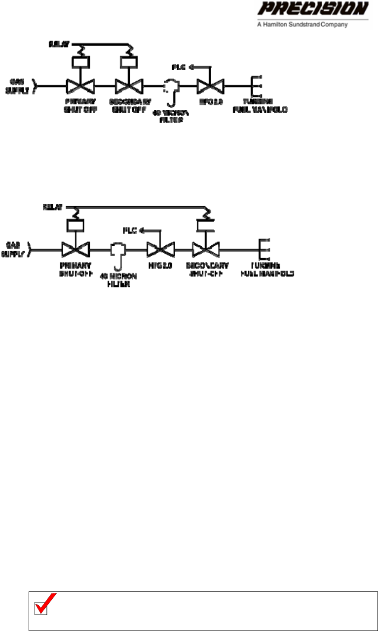
Figure 1-1. Typical HFG2.0 Gas Fuel System Installation
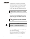
Figure 1-2. Alternate HFG2.0 Gas Fuel System Installation
Dimensions
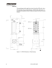
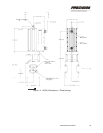
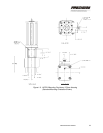
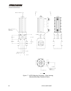
Figure 1-3 and Figure 1-4 show external dimensions for the 3-piece
housing and 1-piece housing versions of the HFG2.0, respectively.
Mounting Considerations
The HFG2.0 can be mounted directly to a gas turbine engine skid using
brackets provided by the engine manufacturer. The HFG2.0 can be
mounted with any directional orientation, whether horizontal, vertical, or at
an angle. The clevis must be supported if the HFG2.0 is mounted
horizontally.
Valve life can be maximized if the HFG2.0 is mounted with the vertical
orientation shown in Figure 1-3 or Figure 1-4, where the valve end is on
the bottom. The drain hole is most effective when mounted in this vertical
orientation.
Note: The one-piece housing version of the HFG2.0 does not
have a drain hole.
INSTALLING THE HFG2.0 5


