


16 HFG2.0 USER GUIDE
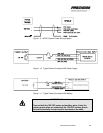
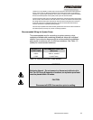
Note: A battery system is recommended for highest reliability.
Note: If a 120 VDC power supply is used rather than a battery,
ensure an output capacitance of at least 12,000 µF, which
can both sink and source electric current. See Power
Supply Requirements (Table 1-2).
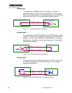
Note: Use a separate conduit for the power wiring. This prevents
noise pickup and transmission from ancillary equipment,
which could cause instability in the actuator.
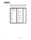
Power Supply Requirements
Table 1-2 below lists the power supply requirements for the HFG2.0.
PARAMETER VALUE
Voltage
Nominal
Range
120 VDC
80 – 160 VDC
Max. Ripple
4 VAC RMS or 12 VAC p-p
Current
Maximum
Continuous , Typical
Transient, Typical
20 Amps
<1 Amp
+20 A <60 ms
+10 A <600 ms
-5 A <100 ms
*Output Capacitance
12,000 µF (typical)
Table 1-2. Power Supply Requirements
*The output capacitance applies for non-battery power systems and assumes full-stroke step
changes in actuator position at rated load. This value is typical. The actual value required is
dependent on the user’s specific DC power system design, including:
• Power sources used in the DC power system (their output impedance, transient response,
rating, diode decoupling [if any], topology, etc.)
• All electrical loads and components connected to each respective power bus branch
• Switching relationships of these electrical loads and components to each other (for example,
does a large motor and actuator turn off at about the same time, etc.)
• Bus branch conductor length and arrangement (flat bus bars, round cables, twisted, etc.)