


4 HFG2.0 USER GUIDE
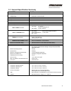
Certifications
North American Certifications CSA Class I, Div 1, Group B, C, D; T4
European Directive Compliance (CE Mark)
EEx d, IIB+H
2
; T4
97/23/EC Pressure Equipment Directive (PED)
94/9/EC Potentially Explosive Atmospheres (ATEX) 02ATEX6051X
98/37/EC Machinery Directive
89/336/EEC Electromagnetic Compatibility Directive (EMC)
Materials
Actuator Housing 6061-T6 Anodized Aluminum
Valve Housing 6061-T6 Anodized Aluminum
316 Stainless Steel (Optional)
Conduit Union Zinc Plated Steel
Seals Viton and Teflon
Connectors Aluminum
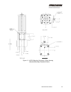
Dimensions 9.7 in x7.7 in x 25.4 in
Weight 100 lbs. Max (Aluminum Valve Housing, 3-piece)
85 lbs. Max (Aluminum Valve Housing, 1-piece)
190 lbs. Max (Stainless Steel Valve Housing, 3 piece)
1.3 Mechanical Installation
This section describes proper HFG2.0 installation. Ensure compliance
with the factory recommendations.
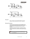
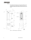
Typical Fuel System
The HFG2.0 installs as part of a gas fuel system as shown in Figure 1-1.
In this arrangement, the HFG2.0 is located downstream from two
normally closed gas shut-off valves.
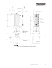
An alternate arrangement is shown in Figure 1-2. In this installation, the
HFG2.0 is located between two normally closed gas shut-off valves.
Fuel Filtering
For efficient valve operation, filter the fuel through a 40-micron absolute
filter before it reaches the valve. This extends the time between routine
maintenance. Locate the fuel filter as close as possible to the valve
INLET.