44 HFG2.0 USER GUIDE
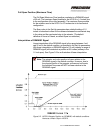
A non-linear interpolation table can be created to define positioning at 16
discrete current levels in the DEMAND signal range, but only during Set
Up using the ActWiz Software. See the Section 3.8 for additional details
about Set Up parameters.
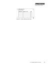
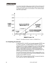
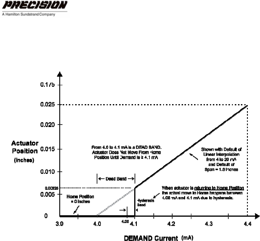
Figure 3-3. Dead Band of Actuator, Position vs. DEMAND Curve
3.6 Resetting the Actuator
To reset the HFG2.0, +24 VDC must be applied across the RESET wires
for at least 0.5 seconds. The leading edge of the RESET command
causes the HFG2.0 to stop all other operations, but the actual resetting of
the HFG2.0 does not begin until RESET is returned to its OFF state. The
RESET command causes the HFG2.0 to reset all internal position
indicators, reload all Set-Up parameters, and check the health of the
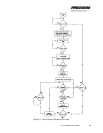
electronics. See the flow chart in Figure 3-1 for an illustration of this. The
HFG2.0 is now in the Power Up / Reset state.
Once the RUN command is detected as ON, the actuator will then move
through its initial homing sequence again. RUN and DEMAND inputs are
ignored during the RESET command.
If FAULT alarm is detected, toggling the RESET command will clear the
FAULT alarm, but it will NOT clear the fault file.


