


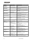
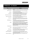

Symptom Probable Causes Corrective Action
RS232 Interface Inoperative Incorrect wiring
No or low 120 VDC power
COM1 not connected
RESET or RUN command is
ON
Ensure WHITE/ORANGE/YELLOW,
WHITE/ORANGE/BLUE, WHITE/ORANGE/GREEN
wires correctly connected to valve and laptop PC.
Ensure 120 VDC Primary System Power at Valve
Check laptop/PC com port
Remove RESET or RUN command
Table 5-1. Initial Installation Troubleshooting Chart
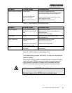
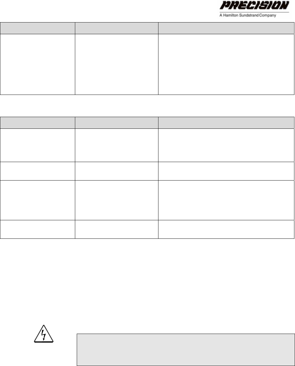
Symptom Probable Causes Corrective Action
No valve feedback No or low 120 VDC power
Self-protective valve auto shut
down
Ensure 120 VDC at valve
Upload Fault File- check for motor windings over -
temperature faults.
Check for valve contamination
FAULT alarm Various Upload Fault File to identify source of fault
Clear indicated fault
OVER TEMP alarm Ambient temperature limit
exceeded
Electronics or motor winding
temperature out of range
Allow actuator to cool and re-start
Reduce ambient temperature
Check for valve contamination
FAULT and OVERTEMP
alarm
No 120 VDC Power
DSP Failure
Ensure 120 VDC at actuator
Contact factory
Table 5-2. HFG2.0 In-Service Troubleshooting Chart
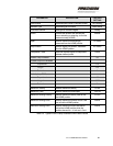
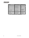
For troubleshooting purposes, use Table 5-3 to verify the valve electrical
continuity integrity.
Disconnect the HFG2.0 power and digital harness connectors and use a
digital multi-meter (DMM) to check the resistance values between the
wires indicated on the table. If an open circuit is detected, send the
HFG2.0 to Precision Engine Controls Corporation for test and repair.
WARNING – Shock Hazard
Remove all power to the HFG2.0 prior to continuity check.
CH. 4: TROUBLESHOOTING THE HFG2.0 57