


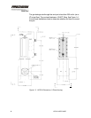
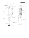
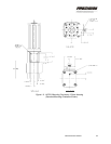
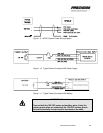
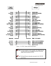
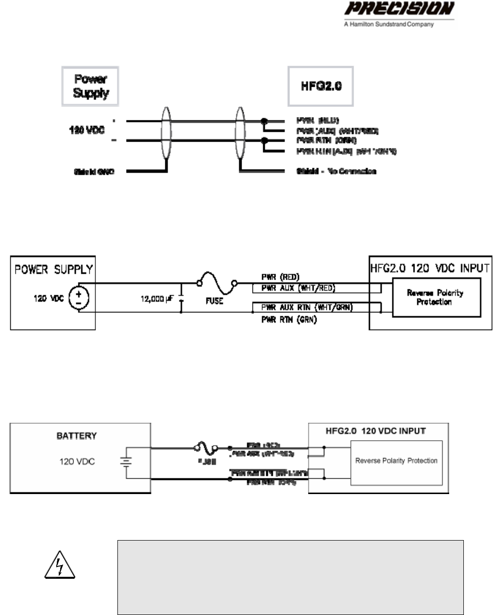
Figure 1-9: HFG2.0 System Power Wiring Diagram
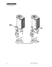
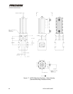
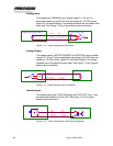
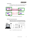
Figure 1-10. Typical Power Connection With Power Supply
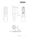
Figure 1-11. Typical Power Connection With Battery
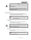
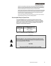
WARNING - Shock Hazard
Connect both the 120 VDC power and auxiliary wires. If only the
primary power wires are connected, the 120 VDC auxiliary power
wires are electrically live and must be insulated on the ends.
INSTALLING THE HFG2.0 15