


Therefore, it is not possible to correctly state a single capacitance value that should be placed on
the bus. It may require no added bus capacitance or hundreds of thousands of microfarads of
capacitance. A typical output capacitance value used for non-battery power systems is 50,000uF,
but the actual value depends on the specific power system as discussed above.
It is best to test the power system for adequate capacitance by executing full-stroke step changes
with the actuator at the same time as all other devices on the bus are switched and measuring the
bus voltage at the actuator power input point to verify that it does not dip below the minimum or
exceed the maximum bus voltage specifications. This test should be performed at both the
minimum and maximum expected operating voltages
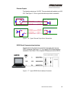
Also, the output capacitance should be carefully positioned so that it is never disconnected from
the HFG2.0 power input during any contact or switching operations.
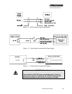
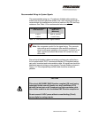
Recommended Wiring for System Power
The recommended wire for connecting to system power is a two-
conductor shielded cable containing twisted-pair wires with individual
shields. Use a wire size large enough to accommodate the installation
and provide a maximum one (1) ohm loop resistance. See Table 1-3
(below) for recommended wire sizes.
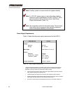
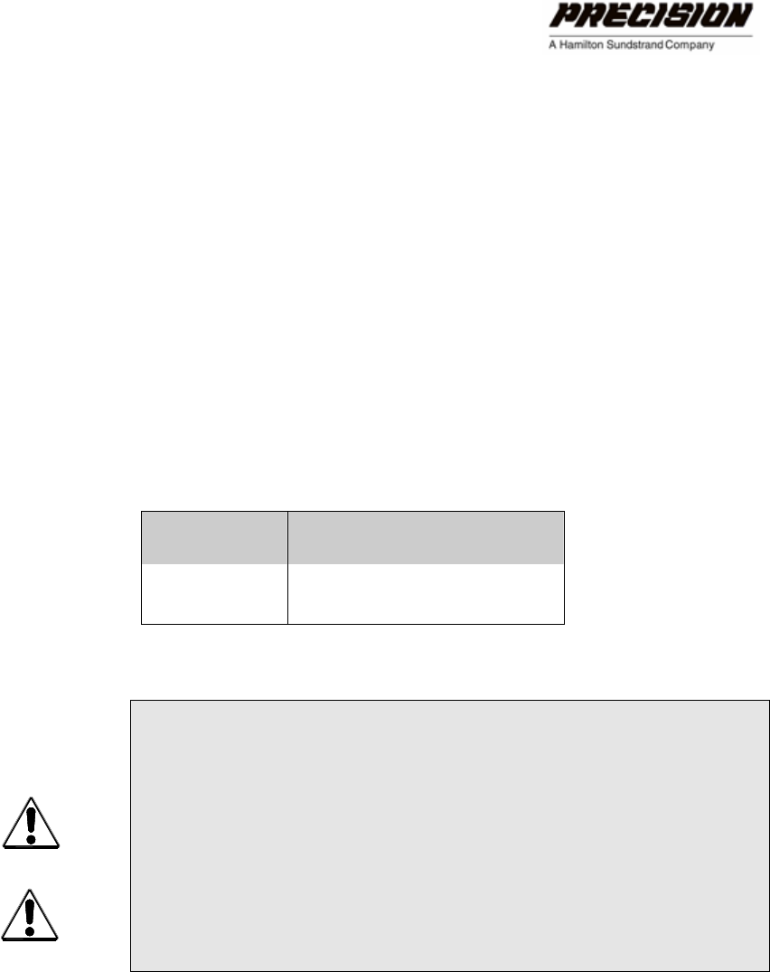
DISTANCE TO
USER POWER
RECOMMENDED WIRE SIZE
(Minimum)
≤ 500 ft. AWG 10, stranded
> 500 ft. Consult Factory
Table 1-3. Wire Size for HFG2.0 Power Harness
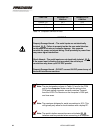
WARNING
Explosion Hazard – Do not connect or disconnect while circuit is
live. For US Group B hazardous locations, an explosion proof seal
must be placed within 18 inches.
CAUTION
Disconnect all HFG2.0 connections prior to welding.
INSTALLING THE HFG2.0 17