


18 HFG2.0 USER GUIDE
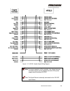
Signal Connections
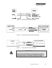
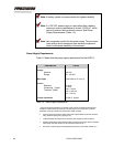
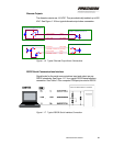
Signals are sent between the HFG2.0 and the user’s controller through
the integral 17-wire signal harness. See Table 1-4 for the wire list for this
harness. See Figure 1-12 for the system signal wiring diagram.
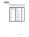
WIRE COLOR FUNCTION AWG
WHITE/ORANGE/YELLOW Serial/RX In 20
WHITE/ORANGE/BLUE Serial/TX Out 20
WHITE/ORANGE/GREEN Serial RETURN 20
BLACK OVER TEMP Alarm 20
WHITE/BLACK OVER TEMP Alarm RETURN 20
ORANGE FAULT Alarm 20
WHITE/ORANGE FAULT Alarm RETURN 20
VIOLET RUN Command 20
WHITE/VIOLET RUN Command RETURN 20
GRAY RESET Command 20
WHITE/GRAY RESET Command RETURN 20
BROWN Position Demand 20
WHITE/BROWN Position Demand RETURN 20
YELLOW Position Feedback 20
WHITE/YELLOW Position Feedback RETURN 20
BLUE Motor Current 20
WHITE/BLUE Motor Current RETURN 20
Table 1-4. Wire List for HFG2.0 System Signal Harness