3 OPERATING THE HFG2.0
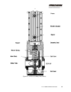
This section refers to the position of the actuator when describing
operation of the HFG2.0 valve. The end of the actuator extension rod is
connected to the poppet assembly of the valve. The linear motion of the
actuator, both extension and retraction, is directly translated to the poppet
assembly. The position of the actuator correlates directly to the position of
the valve poppets relative to the orifices. The Home position of the
actuator is the CLOSED position (zero position) of the valve.
3.1 Powering Up
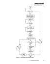
When 120 VDC is applied, the firmware program in the HFG2.0 will clear
all system registers, retrieve all necessary operating parameters from the
electrically erasable programmable read only memory (EEPROM), and
perform an internal status check. This will also happen after a RESET
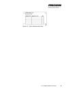
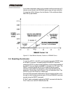
command has been received. See the flow chart in Figure 3-1 for an
overview of this process.
Note: If the HFG2.0 receives a SET-UP command from the
ActWiz software via the RS232 interface after these steps,
the system will transition to the Set-Up state. This state
allows the user to change the Set-Up parameters and to
download the fault file. See Section 3.8 for details.
CAUTION
Always remove the RUN command during power up. If a RUN
command is given during the Set-Up parameter download phase of
power-up, the valve will not respond until the download is complete
and the Home position has been established.
3.2 Finding Home Position
When the program is complete with a status check, it waits for the RUN
command.
When the status check and other steps in the Power-Up/Reset process
are complete, the HFG2.0 will wait until it receives the RUN command. At
CH. 3: OPERATING THE HFG2.0 39


