


ii HFG2.0 USER GUIDE
Figure 1-11. Typical Power Connection With Battery.......................................................15
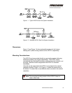
Figure 1-12: HFG2.0 System Signal Wiring Diagram......................................................19
Figure 1-13. Typical Analog Input Connection..................................................................20
Figure 1-14. Typical Analog Output Connection...............................................................20
Figure 1-15. Typical Discrete Input Command Connection .............................................20
Figure 1-16. Typical Discrete Output Alarm Connections ................................................21
Figure 1-17. Typical RS232 Serial Interface Connection .................................................21
Figure 2-1. HFG2.0 Electronics System Block Diagram ..................................................28
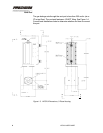
Figure 2-2. HFG2.0 Cut-Away View – Actuator Main Housing Assembly.......................34
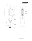
Figure 2-3. HFG2.0 Cut-Away View (Partial)....................................................................35
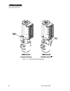
Figure 2-4. Typical Identification Plate...............................................................................36
Figure 2-5. Typical Refurbishment Plate...........................................................................37
Figure 3-1. HFG2.0 Basic Operation Flow Chart..............................................................41
Figure 3-2. HFG2.0 Actuator Position vs. DEMAND........................................................43
Figure 3-3. Dead Band of Actuator, Position vs. DEMAND Curve..................................44
LIST OF TABLES
Table 1-1. Wire List for HFG2.0 Power Harness ..............................................................14
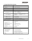
Table 1-2. Power Supply Requirements............................................................................16
Table 1-3. Wire Size for HFG2.0 Power Harness.............................................................17
Table 1-4. Wire List for HFG2.0 System Signal Harness.................................................18
Table 1-5. Computer COM Port Pin Outs .........................................................................22
Table 1-6. Wire Size for HFG2.0 Signal Harness.............................................................23
Table 3-1. Default Configuration For FAULT Alarm ..................................................47
Table 3-2. Default Configuration For OVERTEMP Alarm .........................................47
Table 3-3. Fault Configuration For FAULT Alarm ...........................................48
Table 3-4. Fault Configuration For OVERTEMP Alarm ..................................49
Table 3-5. Typical HFG2.0 Setup Parameters With Default Values................................51
Table 5-1. Initial Installation Troubleshooting Chart..........................................................57
Table 5-2. HFG2.0 In-Service Troubleshooting Chart......................................................57
Table 5-3. HFG2.0 Electrical Continuity Troubleshooting Chart......................................58