32 HFG2.0 USER GUIDE
Extension Rod and Bearings
The extension rod is threaded on the ball nut. As the ball nut translates,
the extension rod moves in and out of the HFG2.0 main housing.
Counter-clockwise (CCW) rotation (facing the motor end of the actuator)
of the motor rotor and screw shaft results in the extension rod extending
out of the main housing. Clockwise (CW) rotation results in the extension
rod retracting back into the main housing.
The extension rod support bearing is provided for lateral support. Thrust
and radial loads are transferred from the extension rod through the ball
nut to the main preloaded duplex thrust bearings. The thrust bearings
transfer the loads to the main housing by the main bearing and shaft
retaining nuts.
A motor end bearing is provided for additional radial shaft stability. The
resolver rotor, motor rotor, motor bearing, and spacers are all stacked on
the ball screw shaft and retained by a single nut. This arrangement
prevents actuator axial loads from passing through the resolver rotor and
motor rotor.
The end of the extension rod is connected to the poppet assembly of the
valve. The linear motion of the extension rod, both extension and
retraction, is directly translated to the poppet assembly.
Valve
The valve portion of the HFG2.0 consists of four main components:
• Valve Housing Assembly
• Orifice Assembly
• Soft Seats
• Return Spring
Valve Housing Assembly
The valve housing assembly may be either three pieces or one piece.
The three-piece version consists of upper, center, and lower valve body
sub-assemblies, which are bolted together with eight, ½” diameter, high-
strength, steel bolts. The assembly is made of either machined aluminum
or stainless steel.
The one-piece version consists of a cast aluminum main pressure vessel
and valve cover assembly. The cover assembly attaches to the bottom of
the vessel. This version does not have a drain port.
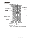
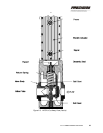
See Figure 2-3.


