


14 HFG2.0 USER GUIDE
1.4 Electrical Connections
The HFG2.0 is suitable for use in hazardous locations. See the General
Specification Summary in Section 1.2 for certifications. Ensure compliance
with the factory recommendations, and that wiring is in accordance with
local requirements.
WARNING:
94/9/EC (ATEX) Compliance – Special Conditions for Safe Use:
Two special factory-sealed unions are mounted on the equipment to
ensure the electrical connection to the network and to provide the
feedback signal to the user.
The installation of these devices and the final connections to the
conduit shall comply with the requirements of the European
standards.
Ground Connection
The case of the HFG2.0 features a threaded hole (0.250-20 UNC-2B
female thread) that is dedicated for the ground connection. This hole has
been left unpainted and uncoated to ensure a good electrical contact.
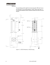
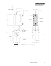
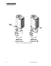
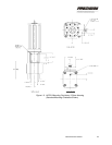
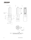
This threaded hole is located on the clevis end of the unit, (see
Figure 1-6, Figure 1-7 or Figure 1-8). Use a screw with a 0.250-20 UNC-
2A thread to connect the case of the HFG2.0 to the same ground plane
as the user’s controller.
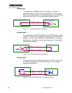
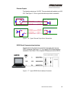
Power Connections
The HFG2.0 operates on a 120VDC (nominal), user-provided input
voltage, which is supplied to the unit through the integral four-wire power
harness. See Table 1-1 for the wire list for the HFG2.0 power harness.
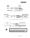
See Figure 1-9 for the HFG2.0 system power wiring diagram. See Figure
1-10 for a typical power connection with a power supply. See Figure 1-11
for a typical power connection with a battery.
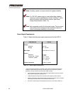
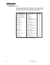
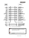
WIRE COLOR FUNCTION AWG
RED Power 14
WHITE/RED Power (AUX) 14
GREEN Power Return 14
WHITE/GREEN Power Return (AUX) 14
Table 1-1. Wire List for HFG2.0 Power Harness