


56 HFG2.0 USER GUIDE
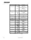
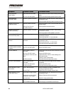
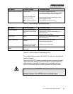
Symptom Probable Causes Corrective Action
Valve Inoperative -
FAULT alarm
Power Wires not connected
No or low 120 VDC power
Ensure RED and GREEN wires correctly connected to
valve
Ensure 120 VDC Primary System Power at valve
Valve Inoperative -
NO FAULT alarm
No RUN or position command Ensure VIOLET and WHITE/VIOLET wires correctly
connected to valve
Ensure 24 VDC RUN and position command at valve
Actuator moves toward
HOME then stops
Intermittent RUN command
Homing Force Too Low
No position demand
Ensure consistent 24 VDC RUN command and fuel
demand signal
Ensure position command at valve
Actuator moves toward
HOME intermittently
Intermittent RESET command Ensure GRAY and WHITE/GRAY wires correctly
connected to Actuator
Ensure consistent 24 VDC RESET command
Actuator finds HOME then
moves to STOP position
No fuel demand signal Ensure BROWN and WHITE/BROWN wires correctly
connected to Actuator
Ensure fuel demand > 2.0 mA at Actuator
Valve does not track fuel
demand
No fuel demand signal or RUN
command
Ensure BROWN and WHITE/BROWN wires correctly
connected to valve
Ensure valve demand > 4.1 mA at valve
Ensure RUN command present at valve
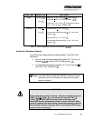
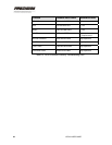
Valve does not hold
consistent position-oscillates
or dithers
Varying fuel demand signal
No or low 120 VDC power
Ensure stable fuel demand at the actuator
Ensure 120 VDC at valve
No valve feedback Valve feedback wires not
connected
No or low 120 VDC power
Self-protective valve auto shut
down
No RUN command
Ensure YELLOW and WHITE/YELLOW wires correctly
connected
Ensure 120 VDC at valve
Upload Fault File- check for motor windings over -
temperature faults.
Check for valve contamination
Ensure RUN command present at valve
No motor current feedback Motor current wires not
connected
No or low 120 VDC power
No RUN command
Ensure BLUE and WHITE/BLUE wires correctly
connected
Ensure 120 VDC at valve
Ensure RUN command present at valve
Valve Operative- FAULT
alarm active
FAULT wiring incorrect
Internal FAULT
Ensure ORANGE and WHITE/ORANGE wires
correctly connected to Actuator
Upload Fault File to identify source of fault
Valve Operative- OVER
TEMP alarm active
OVERTEMP wiring incorrect
Electronics or motor winding
temperature out of range
Valve jammed
Ensure BLACK and WHITE/BLACK wires correctly
connected to valve
Reduce External ambient temperature
Check for valve contamination
Valve leaks when closed Poppet assembly fouled
Valve installed backwards
Stroke valve OPEN and clear foul at orifice
Ensure supply is connected to valve IN port