


Page
6
Model
1000AR Installation and Operation Manual
6/4/2001 © copyright 1997 by Powertec
REFERENCE PAGES
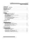
Specifications..........................................................................................................................................2
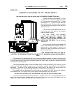
Model 1000AR Standard Connections....................................................................................................4
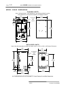
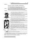
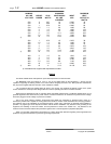
Model 1000AR Dimensions Chart ........................................................................................................10
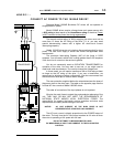
Model 1000AR AC
Input
Electrical Ratings Table ..............................................................................12
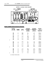
Model 1000AR
Output
Electrical Ratings Table .................................................................................14
Regenerative Resistors .......................................................................................................................16
Contactor Specifications .....................................................................................................................18
Dynamic Braking Resistors .................................................................................................................18
Model 1000AR Control Connections Table .........................................................................................20
Terminal Descriptions List ...................................................................................................................22
PLC Interface Suggestions .................................................................................................................24
Digital Mode Notes ..............................................................................................................................26
Analog Versus Digital Operation Comparison .....................................................................................28
Standard Basic Connection Diagram ...................................................................................................30
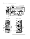
Capacitor Board Location and Layout ..................................................................................................32
Current Controller Board Layout ..........................................................................................................34
Speed Controller Board Layout ............................................................................................................34
Jumpers List .......................................................................................................................................34
LED Indicators - Current Controller Board ...........................................................................................36
LED Indicators - Speed Controller Board..............................................................................................38
Adjustments .........................................................................................................................................40
Simplified Power Schematic ................................................................................................................42
Semiconductor Diagrams......................................................................................................................42
Transistor Module Static Test ...............................................................................................................44
Diode Bridge Test ................................................................................................................................46
Transistor Leakage Test .......................................................................................................................46
Encoder Waveforms and Connections .................................................................................................48
IOC Tests..............................................................................................................................................50
OV/UV Tests.........................................................................................................................................50
Block Diagram - Speed and Current Controller boards .......................................................................52
Base Driver board- Layout and Connections........................................................................................54