Model
1000AR
Installation and Operation Manual
P
AGE
35
OFFICIAL 6/4/2001
WHAT HAPPENS WHEN I …
GIVE THE START COMMAND TO THE MODEL 1000 ?
Before starting the Model 1000AR drive, turn the Current Limit pots fully counter-clockwise, and the
speed reference command input, analog or digital, should be set to zero.
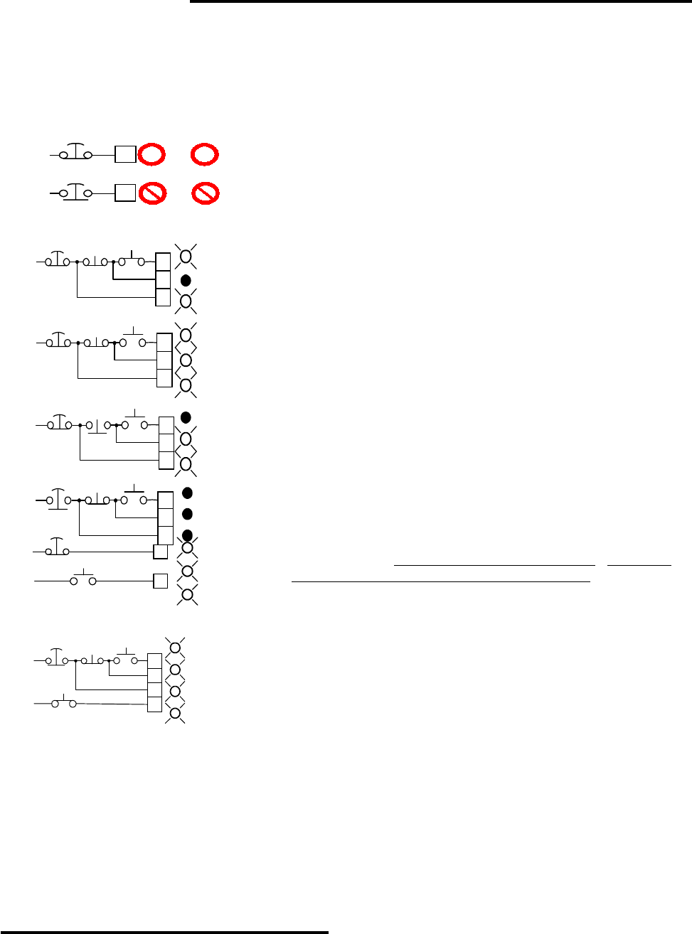
You must have +24VDC (all voltages relative to TB1 terminal
16) applied to TB2-11 (EStop input) before attempting to RUN or
JOG. You must maintain +24VDC on TB2 -11 for as long as you want
to run or jog.. Removing +24V from the Emergency Stop input will
stop the drive regardless of whatever other inputs may be energized.
You must apply +24VDC to TB2 terminal 13 to start
the drive. When you energize TB2-13, even if Emergency
Stop circuit is NOT energized, the RUN LED will lights and
the normally open RUN contact between TB2-1 and TB2-2
closes. If Emergency Stop is closed, the drive stays in RUN
mode as long as +24VDC is maintained on TB2 - 13.
If you use a momentary contact to energize the RUN
input at TB2-13, then you must have +24VDC applied to
TB2- 12 to continue running. If you do not have +24VDC
applied to TB2-12, then the RUN LED goes off and the
contact opens when you release the START button.
If you press the STOP button, or otherwise remove
+24VDC from TB2-12, the drive will go to the ramp stop
mode if the RAMP STOP jumper is installed. The motor will
decelerate to a stop and the drive shuts off.
To shut off immediately, open the Emergency Stop
button or otherwise remove +24VDC from TB2-11.
You start the drive in the JOG mode by applying -24
VDC (from TB2 terminal 9) to TB2 terminal 14. The JOG
LED will light. The RUN LED will NOT light
. The RUN
contact will NOT close at TB2 terminals 7 and 8.
The JOG mode should be initiated from the STOPPED
condition. The JOG mode is locked out in RUN mode.
Place the drive in HOLD mode by applying -24VDC (from
TB2-9) to TB2 - 15. If the drive is stopped, HOLD will turn it
on. HOLD clamps the VCO to zero speed. If the drive is
running, it will decelerate to zero speed in current limit. As long
as HOLD is on, the motor resists turning in either direction.
In JOG, HOLD, or RUN mode, an ENABLE REQUEST is generated, and the ENABLE LED’s should
light on the Current Controller and Speed Controller boards. Reasons why the LED’s may not light:
1. The ENABLE LED will not light if the BUS LED is not GREEN;
2. The ENABLE LED will not light if the EMERGENCY STOP input is not energized;
3. The ENABLE LED will not light if any trip LED on the Current Controller board is lighted:
4. The ENABLE LED will not light if any of the ribbon cables is loose;
5. The ENABLE LED will not light if the RESET JUMPER is in the middle position.
Once the ENABLE LED is lit, turning the motor only requires the insertion of a speed reference.
E.STOP
E.STOP
CLOSED
OPEN
11
TB2
11
TB2
+24VDC
+24VDC
RUN
+
o
JOG
OR
RUN JOG
AND
START
STOP
OPEN
+24V
13
TB2
12
11
OPENCLOSED
RUN
ENABLE
E.STOP
EMERGENCY
STOP
START
STOP
E.STOP
CLOSED
+24V
13
TB2
12
11
CLOSEDCLOSED
RUN
ENABLE
START
+
+
+
E.STOP
START
STOP
CLOSED
+24V
13
TB2
12
11
OPENCLOSED
RUN
ENABLE
RUN
MODE
+
+
0
START
STOP
OPEN
+24V
13
TB2
12
11
OPENCLOSED
RUN
ENABLE
E.STOP
RAMP
STOP
0
+
0
0
0
0
ESTOP
ESTOP
ESTOP
ESTOP
CLOSED
+24V
11
TB2
14
JOG
E.STOP
JOG
-
+
ESTOP
JOG
CLOSED
-24V
ENABLE
START
STOP
CLOSED
+24V
13
TB2
12
11
OPENCLOSED
E.STOP
RUN/HOLD
0
0
0
14
-
HOLD
CLOSED
-24V
ESTOP
RUN
ENABLE
HOLD


