Page
26
Model
1000AR Installation and Operation Manual
6/4/2001 © copyright 1997 by Powertec
DIGITAL MODE NOTES
Since the Brushless DC motor control system is inherently digital, the
performance in the digital mode of operation far exceeds the performance in the
analog mode. In the digital mode the control and motor respond to a frequency
signal fed to the control from an external source.
In the digital mode, we use the same digital control circuitry for the speed
control as we do in the analog mode. The analog output of the accel/decel
circuits drives a voltage-controlled-oscillator (VCO), which in turn feeds the digital
circuitry. We bypass the VCO in digital mode and use an external reference
frequency to control speed.
Activate the digital mode by applying a nominal +24 VDC voltage to TB1
terminal 10, positive with respect to TB1 terminal 9. There is also a jumper next
to P2 on the Current Controller board (141-108) which, when placed in the AF
position, switches the control into the digital mode without energizing terminal 10.
Either of these actions disconnects the control's internal VCO and looks for a
frequency at TB1 terminal 11, which must be positive with respect to TB1 terminal
9. This frequency signal must meet certain specifications:
"ON" VOLTAGE: 18 VDC min, 30 VDC max
"OFF" VOLTAGE: less than 1.5 VDC
FREQUENCY: 2X desired RPM (250 frames or smaller)
DUTY CYCLE: 25% min, 75% max
MAXIMUM FREQ: 50 Kilohertz
10
3
16
You can obtain the best tracking by "ramping" the frequency, that is,
changing the frequency gradually. The motor accelerates in current limit if a
frequency is present when the control starts.
The nature of the Brushless DC motor control is that the motor must return
a pulse for each reference pulse supplied, except in current limit! You will lose
pulses if the control goes into current limit, even for a brief time. So it is best to
not change the external frequency so rapidly that the motor cannot respond
without going into current limit.
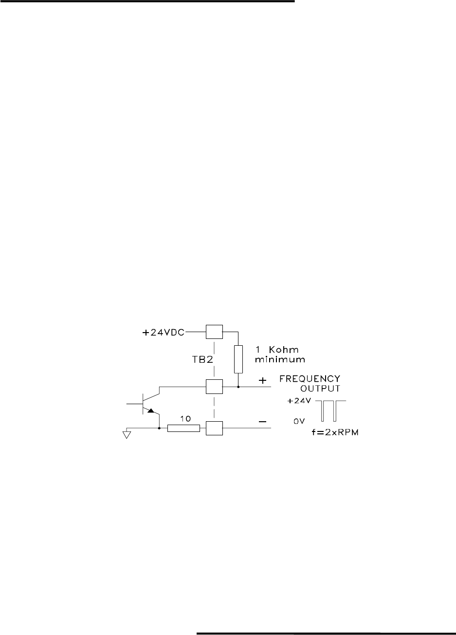
In Digital Mode, you may select the direction of the motor rotation by the
polarity of a voltage at TB2 terminal 5 (2Q/4Q jumper in the 4Q position), or with
the FWD/REV jumper (2Q/4Q jumper in the 2Q position).
