


Model
1000AR
Installation and Operation Manual
P
AGE
33
OFFICIAL 6/4/2001
WHAT HAPPENS WHEN I …
APPLY POWER TO THE MODEL 1000AR ?
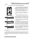
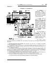
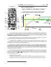
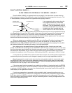
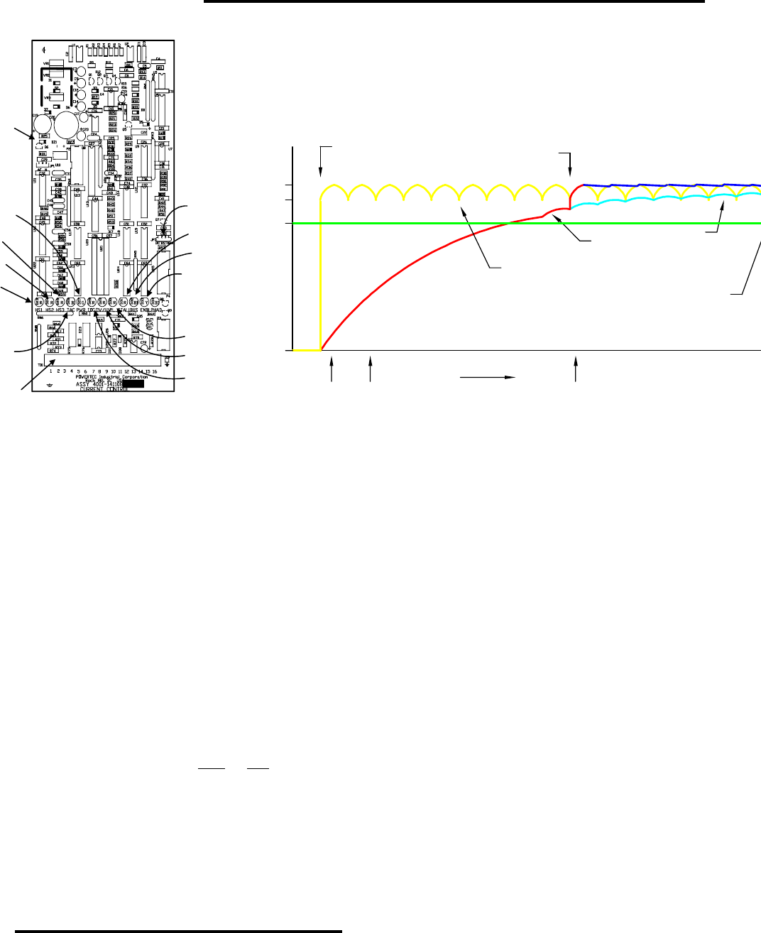
When you apply the power to the Model 1000AR, the graph
below demonstrates what happens to the drive’s bus voltage.
POWER ON
640
VDC
563
VDC
PWR
LED
ON
BUS
LED
RED
BUS
LED
GREEN
VOLTAGE
0
VDC
TIME
CONTACTOR
PULLS IN
OUTPUT
OF DIODE
BRIDGE
BUS
VOLTAGE
BUS
VOLTAGE IF
CONTACTOR
DOES NOT
PULL IN
VDC
540
UNDERVOLTAGE
You can observe the bus voltage with a voltmeter connected to the POSITIVE BUS and NEGATIVE
BUS terminals on the Capacitor Board. This board is located on the right sidewall of the drive behind the
front panels (see page 26). The Bus terminals are near the top of the drive. BE CAREFUL. THESE
TERMINALS MAY HAVE POTENTIALS UP TO 800VDC!!
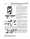
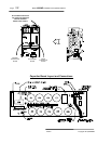
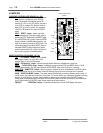
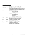
There are LED indicators on the Current Controller board (see the layout on page 28). The action of
some of these LED’s is indicated in the graph above and on subsequent pages.
The POWER LED (it is GREEN in color) comes on as soon as the main power is turned on. This
LED operates from the +24VDC raw power supply. If this LED does not come on, you should check the
incoming power, main fuses and power transformer fuse.
While the bus is charging, the BUS LED lights up RED in color. When the bus reaches a level of
approximately 35VDC below the nominal bus level, a contactor energizes to bypass the charging resistor.
The BUS light then changes to GREEN in color. If the light does not change to GREEN within 30 seconds,
turn off the input power and attach a meter to the bus terminals to monitor the bus voltage. See the
troubleshooting section for assistance.
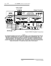
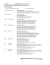
On the Current Controller board, there are three LED’s labeled HS1, HS2, and HS3. These are the
encoder position indicators. One
or two of these indicators should be on. If none are on or if all three are
on, there is a problem. Refer to the troubleshooting section. The TAC LED may be off or RED or GREEN.
It is not important at this time.
The ENABLE LED should be off.
Once the bus has charged up and the BUS LED is GREEN, you may proceed to the next section.
A GREEN LED on the Bus Loader should be ON, but the RED LED on the bus loader must be OFF.
POWER
GREEN
HS3
RED
HS2
RED
HS1
RED
TAC
RED/GREEN
BUS
RED/GREEN
ENABLE
YELLOW
CURRENT CONTROLLER
BOARD
STALL
RED
PL
RED
OV/UV
RED
IOC
RED
TB1
JP1
JP3