


Page
20
Model
1000AR Installation and Operation Manual
6/4/2001 © copyright 1997 by Powertec
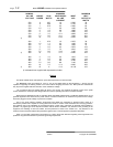
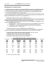
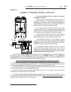
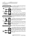
MODEL 1000AR CONTROL CONNECTIONS
MOTOR
THERMAL
STD: CONNECT
FROM
TB2-10 TO TB5-1**
Normally closed thermal switch in the motor. THE MOTOR
THERMAL SWICH MUST BE USED TO PROPERLY PROTECT
THE MOTOR! When the switch opens, the drive must be shut
off to prevent damage to the motor from overheating.
EMERGENCY
STOP
+24VDC ON TB2-11
STD: N/C PB FROM
TB2-11 TO TB5-3**
Voltage must be present to RUN or JOG. When removed,
ENABLE REQUEST is blocked immediately (see page 29) and
all control functions are disabled. Do not connect voltage to
terminal with permanent jumper. In RAMP STOP mode, this is
the only way to stop the drive.
RAMP STOP
+24VDC ON TB2-12
STD: N/C PB FROM
TB2-11 TO TB2-12
Voltage must be present to maintain RUN mode after a
momentary START is removed. When voltage is removed, the
drive decelerates to zero speed at the DECEL rate and shuts
off if RAMP STOP jumper JP2 is installed. Otherwise drive
shuts off immediately and the motor coasts to a stop.
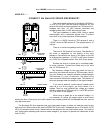
START /
RUN
+24VDC ON TB2-13
STD: N/O PB FROM
TB2-12 TO TB2-13
Voltage must be applied to initiate RUN mode. When it is
removed, drive shuts off unless +24VDC is present at TB2-5.
RUN LED turns on when +24VDC is applied to TB2-4. RUN
LED turns off and RUN relay drops out when voltage is
removed from both TB2-4 and TB2-5.
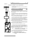
RUN
CONTACT
TB2-7 AND TB2-8
Normally open dry contact closes when START is energized
and opens when RUN relay drops out. The RUN contact does
not open on a FAULT. The RUN contact does not close on
JOG and opens in RAMP STOP mode.
ZERO
SPEED
OUTPUT: TB2-1
COMMON: TB2-16
Open collector transistor output referenced to TB2-12. Rated
at 50 mADC @ 50 VDC max. This output operates only in RUN,
JOG, or RAMP STOP modes. The ZERO SPEED output turns
on at about 10 RPM and off at about 5 RPM. The ZERO
SPEED output shuts off if the ENABLE LED shuts off.
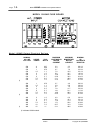
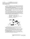
JOG
-24VDC ON TB2-14
STD: N/O PB FROM
TB2-9 TO TB2-14
Voltage must be applied to initiate JOG mode. JOG mode will
be maintained only as long as the voltage is present. When
the voltage is removed, the drive will go to RAMP STOP mode
if COAST TO STOP jumper JP2 is installed. Otherwise the
drive shuts off and the motor coasts to a stop.
HOLD
-24VDC ON TB2-15
STD: N/O PB FROM
TB2-9 TO TB2-15
When the voltage is applied, the output of the Voltage
Controlled Oscillator is reduced to zero PPR. This causes the
drive to decelerate to zero speed in current limit and hold
there. When the voltage is removed, the drive accelerates
back to set speed in current limit.
NOTICE: The drive is NOT OFF in the HOLD
NOTICE: The drive is NOT OFF in the HOLDNOTICE: The drive is NOT OFF in the HOLD
NOTICE: The drive is NOT OFF in the HOLD function.
function. function.
function.
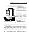
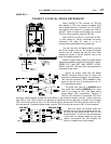
FAULT
OUTPUT
OUTPUT
COLLECTOR: TB1-12
EMITTER: TB1-13
Optically coupled transistor output (isolated). Rated at 50
mADC @ 50 VDC. Turns on when bus has achieved proper
level. Output is off when any trip occurs.
ANALOG/
DIGITAL
SWITCH
+24VDC ON TB1-10
REFERENCE TB1-9
TB1-9 IS NOT DRIVE
COMMON
Apply voltage to switch to DIGITAL mode. TB1-10 and TB1-9
are electrically isolated from the board power supplies. The
negative side of the +24VDC used for the input must be
connected to TB1-9. External frequency must be applied to
terminal 11. Terminal 9 is also common for this frequency.
** Note:
TB5 is on the Bus Loader. The Small Bus Loader interlock is TB5-1 and TB5-3.
The large Bus Loader interlock is TB5-1 and TB5-2.