


Page
18
Model
1000AR Installation and Operation Manual
6/4/2001 © copyright 1997 by Powertec
CONTACTOR SPECIFICATIONS
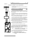
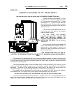
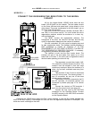
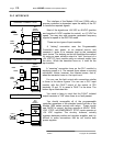
If you want to operate an Output or DB Contactor directly
from the Model 1000AR, you must choose a coil that draws
less than 50 milliamps DC.
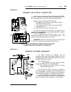
The Output Contactor drawing on page 11 shows the
connections for direct operation of the contactor (use the
same connections for Dynamic Braking). The coil must be
48VDC and draw less than 50 ma DC (2.4 Watts). This is the
most power available from the Model 1000AR drive’s supplies.
To use a 115VAC or 230 VAC coil, you need a 156-012
Contactor Control board, as shown in the drawing on page 11.
Use the same drawing for the Output Contactor. Maximum
current for the Contactor Control board is 1 Amp at 230 VAC.
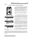
You need three normally open power poles and a normally
open auxiliary for an Output Contactor. The contactor does
not make or break with current in the power contacts. Choose
the contact ratings only on the basis of carrying the current.
For Dynamic Braking, you need three normally closed
power poles and a normally open auxiliary. The contacts make
with current present, but they do not break current in the
dynamic braking operation. Choose contacts accordingly.
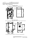
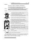
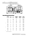
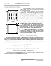
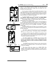
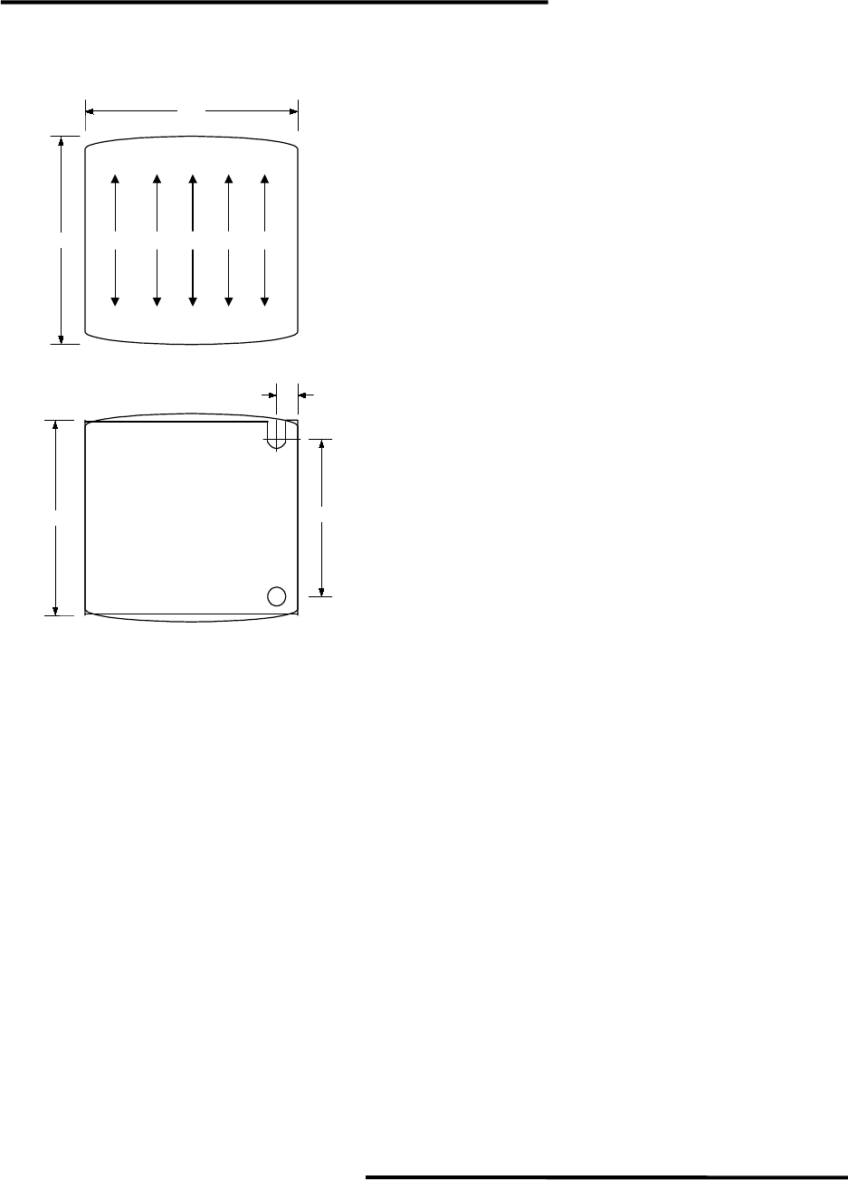
The contactor outline sketched at left is from the SH-04
series by AEG Industries. The model used for the Output
Contactor is part number SH-04.40 and the Dynamic Braking
is SH-04.13. Contact ratings are 16 Amps.
DYNAMIC BRAKING RESISTORS
We choose DB resistors for their ability to absorb high inrush currents and to accept large amounts of
power for short periods of time. Typical DB resistors can absorb ten times their power rating for up to five
seconds. The resistors must then cool down to ambient temperature before they can dissipate their full
rating again (usually a few minutes). It is possible to extend the ratings by about three times with power
resistors by forced-air cooling.
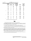
You can derive an approximate value of dynamic braking resistor from the bus voltage and the full
load current on the nameplate of the motor:
Bus Voltage X 0.47
Each Resistor Value ~ -----------------------------------
Motor FLA
Three resistors (or groups of resistors) are necessary. The power rating of each should be:
Power > 0.02 X (Buss Voltage)
2
/ (Resistor Value)
These formulas are very general, and results will vary from motor to motor. For dynamic braking
tailored to your application, consult
POWERTEC
Engineering.
1.77"
1.66"
13 21 31 41
A1
14 22 32 42 A2
TOP VIEW
BOTTOM VIEW
1.25"
0.19"
1.54"