Page
54
Model
1000AR Installation and Operation Manual
6/4/2001 © copyright 1997 by Powertec
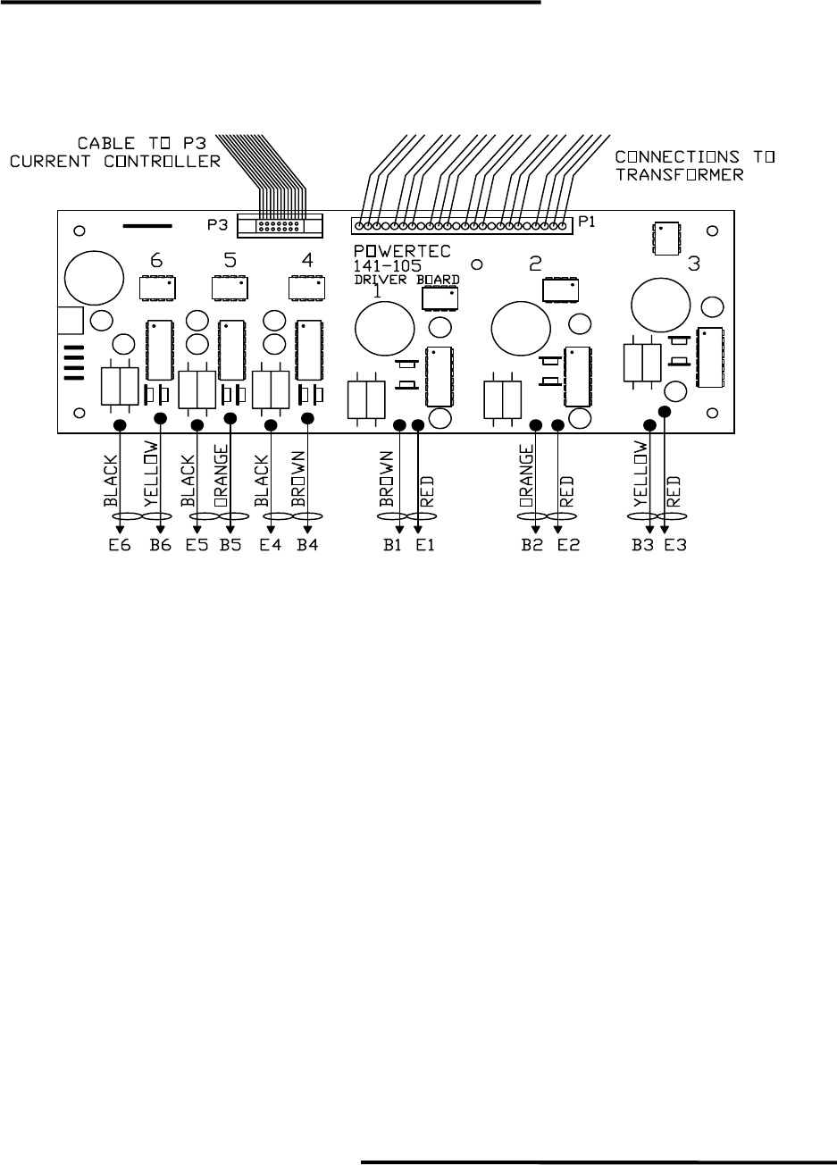
DRIVER BOARD LAYOUT AND CONNECTIONS
DRIVER BOARD LED’S
The base driver board LED’s turn on when current is being supplied to the bases of
the output power transistors.
For output transistor numbering, see the Simplified Power Schematic drawing on
page 32.
On the Model 1000 series non-regenerative drives, transistors #1, #2, and #3 (
referred to as the “top” transistors because they are connected to the positive side of the
bus) are “block fired”, i.e., they are on continuously while the motor is in a position where
they should be on. On a four-pole motor (standard motors with frame sizes from 42T
through 259T), each of the output transistors 1, 2, and 3 are on for 60 degrees of shaft
rotation. This makes the LED’s for transistors 1, 2, and 3 easy to see while the motor is
running.
Transistors #4, #5, and #6 are each enabled for 60 degrees of shaft rotation while
the motor is in the corresponding position, but the output transistor is controlled by a
“pulse-width modulation” (PWM) which is determined by the motor current required.
Under light loads, this means that the transistor may only be on 1 percent of the time. The
LED’s for #4, #5, and #6 (referred to as the “bottom” transistors because they are
connected to the negative side of the bus) therefore, may be difficult to see. As the load
increases on the motor, observation becomes easier.
The best way to check the LED’s on the Base Driver Board is to disconnect the
motor power leads T1, T2, and T3, start the drive, and rotate the motor shaft by hand.
Then all of the LED’s will come on at full brightness.
