


Model
1000AR
Installation and Operation Manual
P
AGE
23
OFFICIAL 6/4/2001
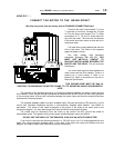
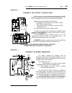
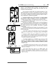
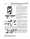
The RUN relay contact at TB2 terminals 7 and 8 is a dry contact
rated at 1 Amp (Resistive load) at 125VAC. You may use it in an
external circuit as long as the voltage does not exceed 125 VAC
(limitation of the terminal strip).
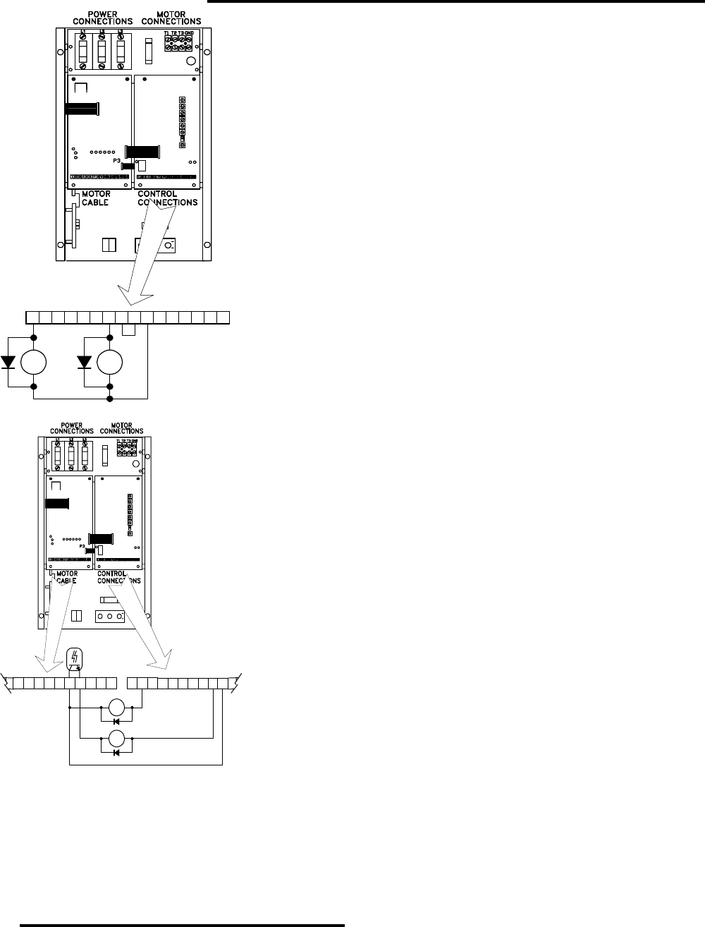
You may use an auxiliary relay if you need more power, or if you
need more contacts, as shown in the drawing at the left. You should
use a 48VDC coil (highly recommended) since this reduces the burden
on one supply. The diode is a general purpose type rated for at least 1
Amp at 100VDC PIV (1N4002 or equivalent).
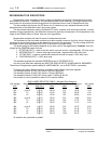
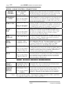
The ZERO SPEED output at TB2 terminal 1 is an open collector
NPN transistor, rated at 50 ma at 50 VDC. The ZERO SPEED
transistor turns on at about 10 RPM and turns off at about 5.RPM
The transistor emitter is at drive common and it may interface
directly with a PLC as a sinking input.
The output can operate a relay as shown in the top drawing on
the left. The transistor returns to drive common, so it is not possible to
use a 48VDC relay with the drive’s supplies. If you use a 24VDC relay,
the current must be as low as possible. The diode is a general
purpose type.
The ZERO SPEED relay will chatter at very low speeds. You can
overcome this with a latching circuit that releases at the first dropout of
the zero speed relay.
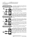
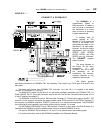
The FAULT output at TB1 terminals 12 and 13 is the output
transistor of an optical coupler. The coupler’s rating is 100VDC @ 50
ma.
Connect a FAULT relay with a 48VDC coil as shown in the
bottom figure at left. The external FAULT relay energizes when the
drive completes power-up and de-energizes when a fault occurs.
The diode is a general purpose diode.
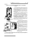
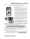
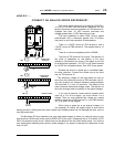
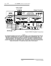
The Model 1000AR has an ENABLE output terminal at TB2
terminal 2. The ENABLE output is an open collector transistor that
turns on when the drive is ready to accept a reference for speed
input, whether in RUN or in JOG. You must use a 24VDC coil on the
ENABLE output.
The ENABLE output shuts off if there is a trip or when the drive
shuts off either on Emergency Stop or a non-ramp stop, or when the
JOG input is released.
The internal RUN relay drops out on RAMP STOP. The
ENABLE output remains energized throughout the RAMP STOP
sequence. Use ENABLE for functions which must continue when the
motor is running.
TB2
16151413121110987654321
R+ R-
ZERO
SPEED
RELAY
24VDC Coil
RUN
RELAY
48VDC Coil
R+ R-
TB1
16151413121110987
FAULT
OUTPUT
ISOLATOR
48V
DC
24V
DC
9321
TB2
ENABLE
FAULT
-24VDC
116 654 87 10
+24VDC
ENABLE