


Model
1000AR
Installation and Operation Manual
P
AGE
15
OFFICIAL 6/4/2001
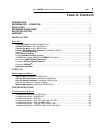
HOW DO I …
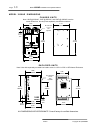
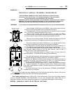
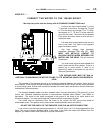
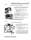
CONNECT THE MOTOR TO THE 1000AR DRIVE?
We ship every drive from the factory with A STANDARD CONNECTIONS card.
Connect the motor lead marked T1 to the
T1 terminal on the drive. Connect the T2 lead
to T2 on the drive, and connect T3 to T3. Other
connections to T1, T2, and T3 at the motor will
vary with the motor. The motor will not operate
if the power wires from motor to drive are not in
the proper order.
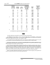
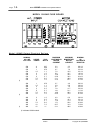
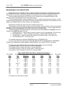
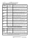
Full load motor current determines the wire
size to the motor. The table on the opposite
page lists these currents.
Any high voltage, high frequency
equipment generates EMI and RFI.
YOU
MUST USE METALLIC CONDUIT TO
ENCLOSE MOTOR WIRES
BETWEEN THE
MOTOR AND THE DRIVE.
This will minimize
interference.
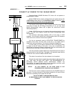
You must install a ground wire between the
motor frame and the drive chassis. There is a
ground lug in most motors. If there is no
ground lug, make a connection at any bolt in
the motor junction box.
THIS GROUND WIRE MUST BE RUN IN
ADDITION TO GROUNDING THE MOTOR FRAME TO ITS MOUNTING, WHICH IS REQUIRED BY
CODE.
The purpose of this separate ground is to equalize the potential between the motor's frame and the
drive chassis. There may be enough impedance to broadcast EMI and RFI even with the motor grounded
to its mounting frame. A direct wire connection between the motor frame and the drive chassis minimizes
interference in other equipment.
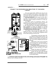
The encoder feedback cable must be a shielded cable. Connect the shield to TB1 terminal 1 on the
control end. Standard installation requires a nine-conductor shielded cable (Belden
™
part #9539 or
equivalent). The colors of this cable correspond to the colors of the wires in the motor and on the
connection diagram. You may interchange the Purple and White wires without ill effect.
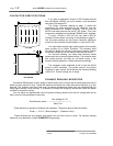
The shield must be continuous from the motor to the control. Do NOT ground the shield at
intermediate points. This applies to all junction boxes installed between motor and control.
DO NOT USE THE SHIELD OF THE ENCODER CABLE AS AN ACTIVE CONDUCTOR!
If you want to use the motor thermal protector in a 120 VAC circuit, run it in wiring separate from the
cable. Use seven-conductor shielded cable. In this case, if the cable wire colors are different from the
diagram, you need to check them carefully for proper connections.
R+R-
BLDC
MOTOR
T1 T2 T3
GND
1 2 3 4 5 6 7 8 9 S
Blue
Brown
Black
Orange
Red
Green
Yellow
16
1 2 3 4 5 6 7 89
TB1
18
1 2 3 4 5 6 7 89
TB2
Purple
White