


Model
1000AR
Installation and Operation Manual
P
AGE
51
OFFICIAL 6/4/2001
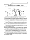
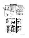
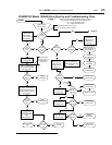
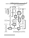
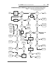
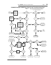
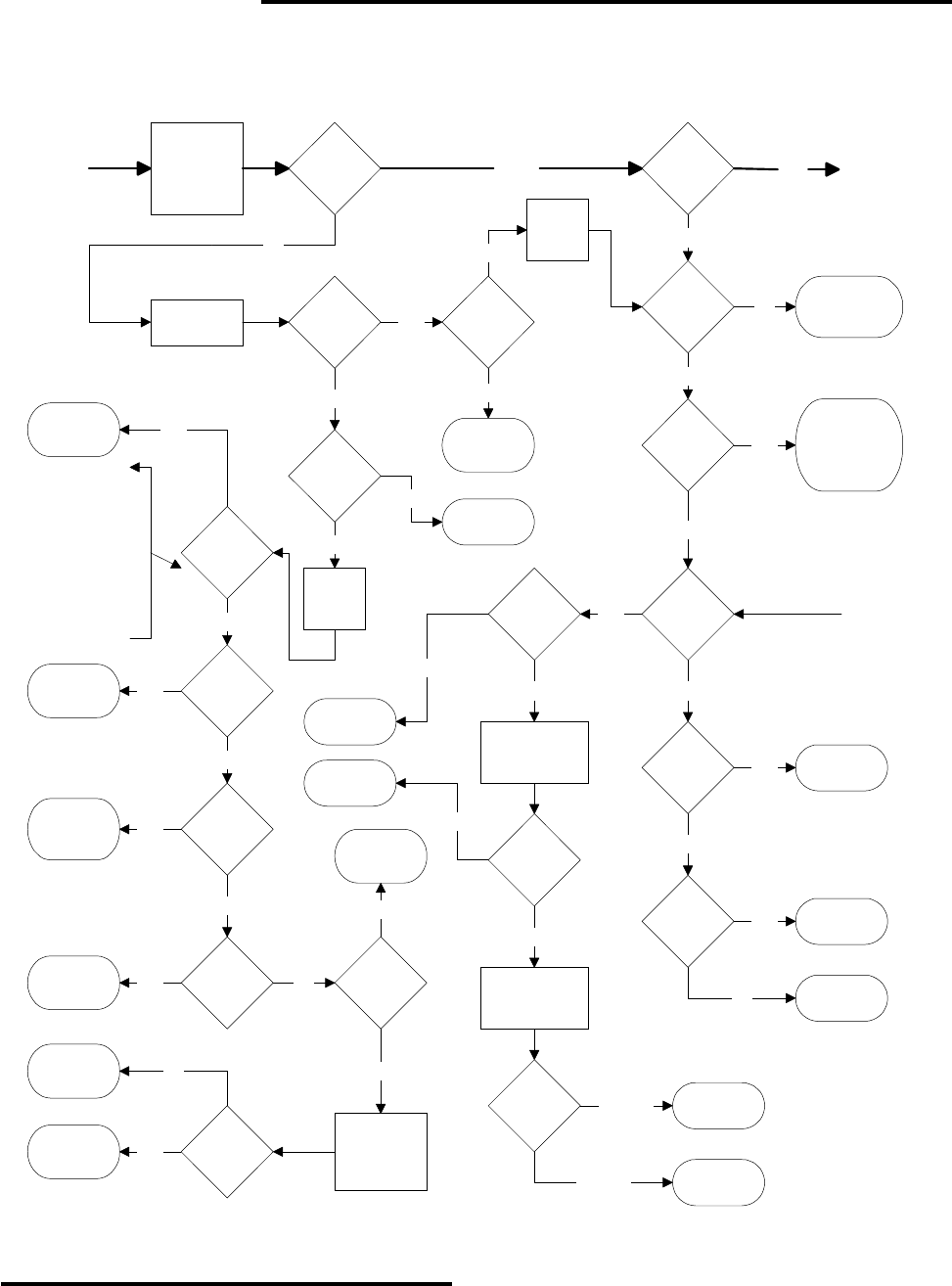
POWERTEC Model 1000AR Drive Start Up and Troubleshooting Chart
NOTE: This chart assumes standard control connections
and no options installed which affect speed control.
CC = Current Controller board.
Is
RUN LED
ON
?
To
Page 5
From
Page 3
Page 4
Is
ENBL LED
ON
?
Press START
Button and
Release
(See note
above)
+24V
TB2-13(+)
TB2-16(-)
?
+24V
TB2-12(+)
TB2-16(-)
?
Check
"START Button"
connections
No
+24V
TB2-11(+)
TB2-16(-)
?
Yes
Check
"STOP Button"
connections
No
+24V
TB5-3(+)
TB2-16(-)
?
Yes
Check "EMERG
STOP Button"
connections
No
+24V
TB5-1(+)
TB2-16(-)
?
Yes
Check Bus
Loader for
Green LED
Disconnect all
wires connected
to TB2-10
+24V
TB2-10(+)
TB2-16(-)
?
Yes
Check
disconnected
wires
Replace Speed
Controller Board
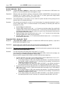
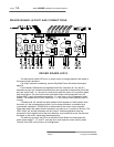
This sequence
assumes that standard
control connections
are being used.
See page 21.
The voltages given
must be at the
indicated terminals
unless otherwise
indicated.
No
Yes
Press and
HOLD START
Button
Is
RUN LED
ON
?
No
Replace Speed
Controller Board
+24V
TB2-11(+)
TB2-16(-)
?
Yes
+24V
TB2-12(+)
TB2-16(-)
?
No
No
Check
"STOP Button"
connections
Yes
No
Check "EMERG
STOP Button"
connections
Yes
Release
START
Button
Release
START
Button
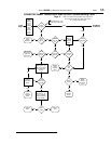
No
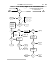
PJ1
on CC
in RESET
position
?
Yes
Set PJ1 jumper on
Current Controller
board to either INT
or MAN position
No
Is
PL LED
on CC
ON
?
No
Yes
+24V
TB2-10(+)
TB2-16(-)
?
Replace Current
Controller Board
>21VDC
<21VDC
No
Yes
Shut off power
Unplug P3 and TB2
Reapply power
+24V
TB2-10(+)
TB2-16(-)
?
Replace Speed
Controller Board
>21VDC
Shut off power
Plug In P3
Reapply power
+24V
TB2-10(+)
TB2-16(-)
?
<21VDC
Replace
Capacitor Board
Check TB2
Connections
>21VDC
Is
IOC LED
on CC
ON
?
No
Is
OVUV
LED on CC
ON
?
Perform IOC
tests (page 50)
Yes
Perform OV/UV
tests (page 50)
Yes
Replace Cable
on P3 Connector
No
TRIP
+24V
TB2-10(+)
TB2-16(-)
?
No
No
<21VDC
Check Motor
Thermal and
wires
Yes
Yes
Yes