


Page
22
Model
1000AR Installation and Operation Manual
6/4/2001 © copyright 1997 by Powertec
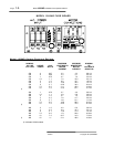
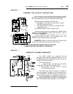
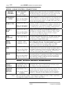
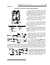
TERMINAL DESCRIPTIONS - MODEL 1000AR
TB1 Current Controller Board (141-108)
1 Dedicated Shields and Ground connection
2 HS1 position encoder
3 HS3 position encoder
4 HS2 position encoder
5 HS4 speed encoder
6 HS5 speed encoder
7 Encoder Common for encoder ONLY
8 Encoder +5 VDC for encoder ONLY
9 Isolated Common for terminals 10 and 11
10 Auto/Manual Selection +24 VDC for Digital Mode
11 External Frequency Input +24 VDC Square Wave
12 Collector of FAULT transistor
13 Emitter of FAULT transistor
14 Drive Load output -2VDC = 150%
15 Auxiliary Supply output +15VDC for extra encoder
16 Power Supplies Common
TB2 Speed Controller Board (147-101)
1 ON at zero speed (open collector) 30VDC 50 mA maximums
2 ON when enabled (open collector) 30VDC 50 mA maximums
3 Speed Output (open collector) 30VDC 50 mA maximums
4 -10VDC Reference Source 5 mA maximum
5 Speed Reference Input -10VDC to +10VDC
6 +10VDC Reference Source 5 mA maximum
7 RUN output contact N/O 125VAC
8 RUN output contact N/O 1A Resistive
9 -24VDC supply 50 mA maximum
10 +24VDC supply 50 mA maximum
11 EMERGENCY STOP Input +24VDC to activate
12 RAMP STOP Input +24VDC to activate
13 RUN/START Input +24VDC to activate
14 JOG Input -24VDC to activate
15 HOLD Input -24VDC to activate
16 Signal Common
TB3 Capacitor Board (141-106)
1 Horsepower calibration resistor
2 No connection
3 Horsepower calibration resistor
TB5 Bus Loader (Integral unit connected to Driver board)
1 Bus loader Interlock N/O 125VAC
2 No connection
3 Bus loader Interlock N/O 1A Resistive
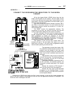
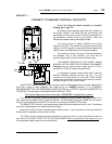
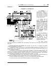
HOW DO I …
GET RUN, ZERO SPEED, FAULT AND ENABLE INFORMATION?