


Model
1000AR
Installation and Operation Manual
P
AGE
25
OFFICIAL 6/4/2001
HOW DO I …
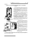
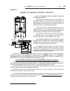
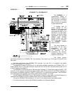
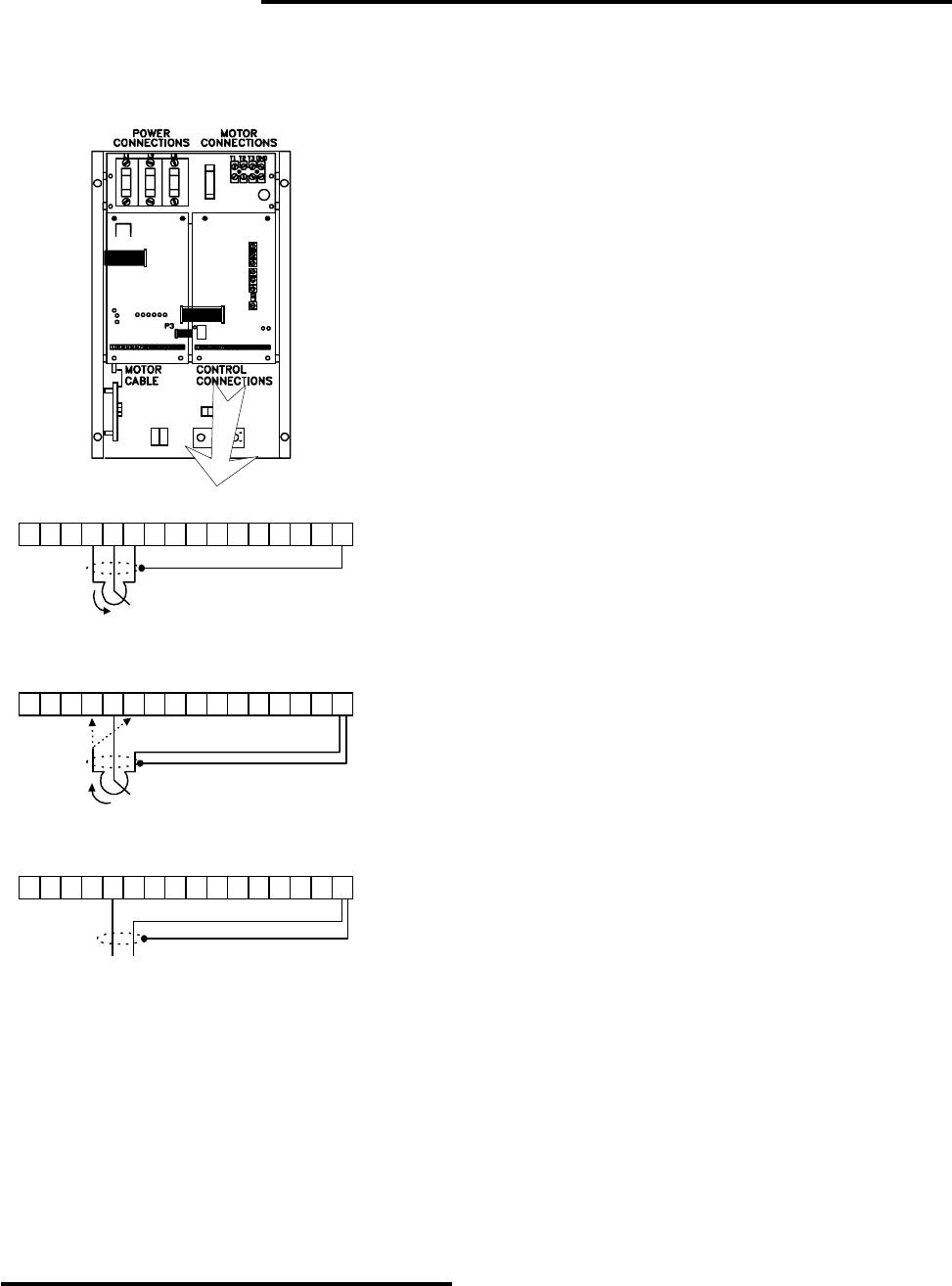
CONNECT AN ANALOG SPEED REFERENCE?
The analog speed reference for the Model 1000AR is -
10 VDC to +10 VDC with the positive connection on TB2
terminal 5 and the common connection on TB2 terminal 16.
Voltages less than -10 VDC become non-linear and
voltages greater than 10 VDC become non-linear.
The input impedance is about 100K. Using a speed
potentiometer with a resistance greater than 10 Kohms
may result in non-linear operation of the speed pot.
There is a 10VDC source at TB2 terminal 4 and a
+10VDC source at TB2 terminal 6. The supplies have a 10
ma limit.
There is no minimum speed pot on the 1000AR.
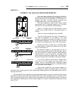
The input at TB2 terminal 5 is bi-polar. The direction of
the motor is dependent on the polarity of the input
reference. Connections are shown in the figure on the left
for bi-directional operation (-10 VDC for full speed forward
to +10VDC for full speed reverse. Zero VDC is zero speed.
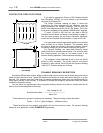
Enclose the wires to a speed pot in a shielded cable,
for noise reduction. Connect the shield only at the drive
end, on TB2 terminal 16.
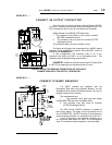
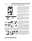
The reference voltage for the input does not have to
come from the reference sources at TB2 terminals 4 and 6.
You can introduce an external reference voltage between
TB2 terminals 5 (+) and 16 (common). The speed of the
motor varies as the external voltage varies. The direction of
the motor changes when the polarity of the signal changes.
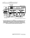
If you use an external “current source” speed control
(such as a 4 to 20 ma signal), you must convert it to a
voltage. Then you may introduce this voltage as a speed
reference command to TB2 terminal 5 (+) and TB2 terminal
16 (-), as shown in the diagram.
When using a speed pot or an external voltage, it is
not necessary to reduce the speed signal to zero before
starting the drive. Starting the drive with a speed input already present will not damage the drive, even at
very high accel rates.
The Brushless DC drive operates over very wide speed ranges, so when you want the motor to stop
with the drive in RUN mode, there must be ZERO VDC at the input. Voltages as low as 70 millivolts (0.070
VDC) will cause the motor to turn. Noise levels on the reference line can reach these values. You must be
very careful about shielding and common mode voltages if you expect to operate with references of less
than 0.5 VDC.
R+ R-
+10VDC
-10VDC
REF IN
TB2
SPEED POT
10K
CW
16151413121110987654321
BI-DIRECTIONAL
OPERATION
+10VDC
-10VDC
REF IN
TB2
SPEED POT
10K
CW
16151413121110987654321
UNI-DIRECTIONAL
OPERATION
CW
CCW
REF IN
TB2
16151413121110987654321
0 TO 10VDC
REFERENCE
+
-
EXTERNAL SOURCE