


Model
1000AR
Installation and Operation Manual
P
AGE
47
OFFICIAL 6/4/2001
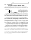
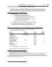
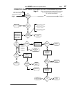
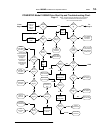
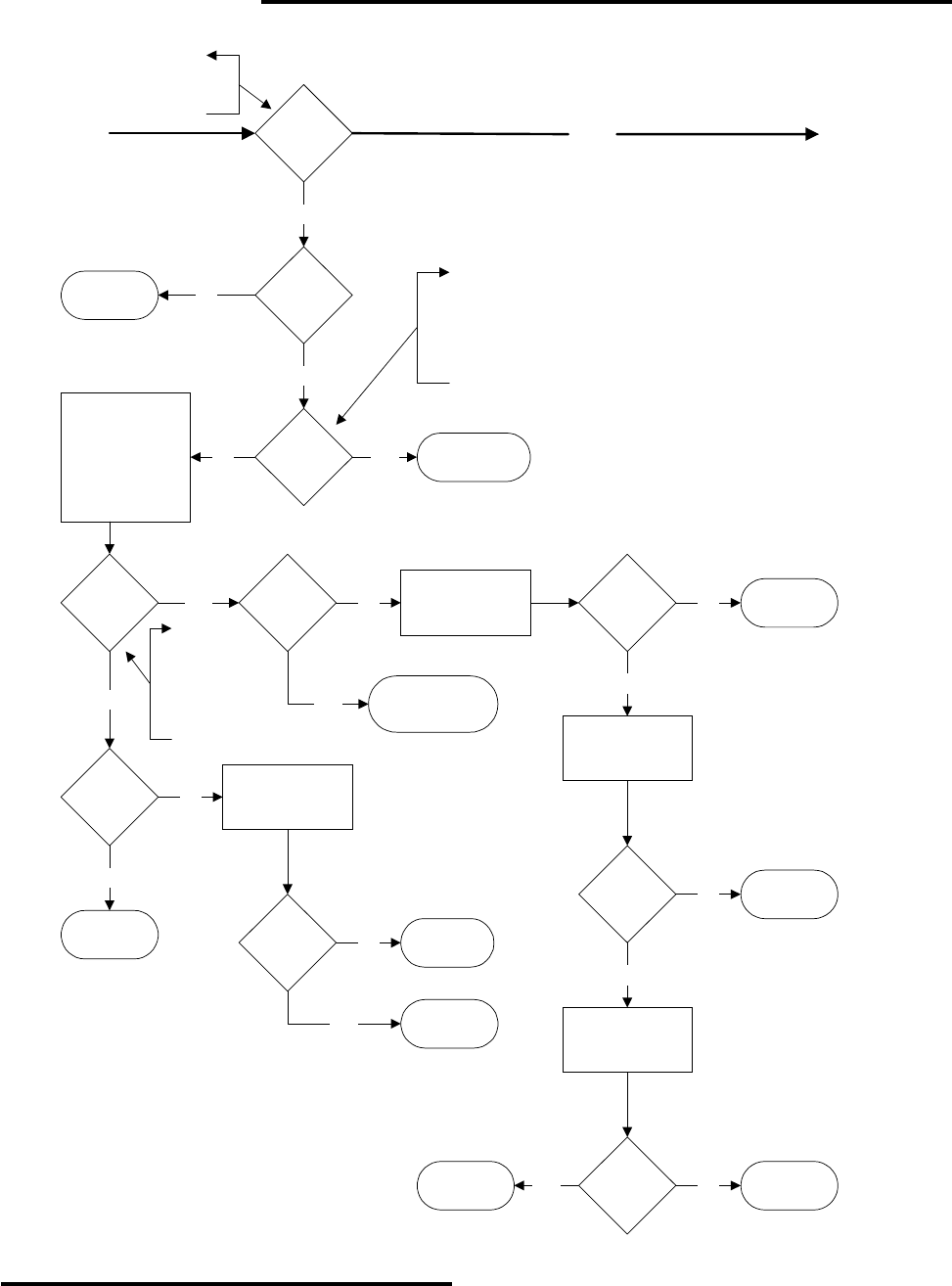
POWERTEC Model 1000AR Drive Start Up and Troubleshooting Chart
NOTE: This chart assumes standard control connections
and no options installed which affect speed control.
CC = Current Controller board.
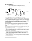
Is
BUS LED
GREEN
?
To
Page 3
Wait up to 30 seconds for
BUS LED to change from
RED to GREEN
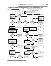
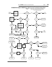
From
Page 1
No
Is
BUS LED
RED
?
No
Replace Current
Controller board
No
Disconnect Motor
Measure the Bus
Voltage between
POSITIVE BUS Tab
and the NEGATIVE
BUS Tab on the
Capacitor Board.
Is
Bus
VDC
< 10%
?
No
Is
Charge
Fuse OK
?
Line VAC = 230
Bus VDC = 320
Line VAC = 380
Bus VDC = 530
Line VAC = 460
Bus VDC = 640
Yes
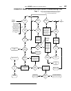
Turn Power Off
Remove FU1 on
Capacitor Board
No
Replace
Charge Fuse
Replace
Capacitor Board
Yes
Bus
Loader
Connected
?
Disconnect
Bus Loader and
Start Over.
No
Yes
Is
Bus
VDC
> 90%
?
Yes
No
Replace
Transistor
Module
Turn Power Off
Perform Diode
Bridge Test
Is
Diode
Bridge OK
?
Yes
No
Replace Diode
Bridge
Turn Power Off
Check Choke L1
for continuity
Is
Choke
OK
?
Perform
Transistor Module
Leakage Test
Is
Transistor
Module
OK?
Yes No
Replace
Choke
No
Replace
Capacitor Board
Yes
Is
Line
Voltage
Too Low
?
Yes
Yes
Fix Line Voltage
Problem
Replace
Capacitor Board
Nominal Line Voltage = 230VAC
Too Low < 208 VAC
Nominal Line Voltage = 380VAC
Too Low < 342VAC
Nominal Line Voltage = 460VAC
Too Low < 415VAC
Page 2
Yes