


Model
1000AR
Installation and Operation Manual
P
AGE
21
OFFICIAL 6/4/2001
HOW DO I …
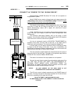
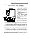
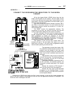
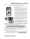
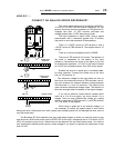
CONNECT STANDARD CONTROL CIRCUITS?
If you are using an output contactor or dynamic
braking, go to page 19.
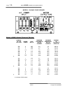
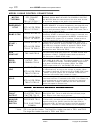
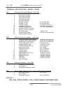
The table on the opposite page lists the functions of
the Model 1000AR. The table lists the connections and
descriptions of the control circuits. Read the descriptions of
the operations of these circuits very carefully. There are
differences between analog and digital modes.
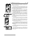
The control circuits of Model 1000AR motor control
operate on 48 VDC. This results from using the positive and
negative 24 VDC supplies. Using 48VDC helps balance the
load of relays and other devices on the power supplies.
The maximum current from each of the raw supplies is
50 milliamps. Due to this limitation, you must use an
external supply when you use several external relays.
THE POWER SUPPLIES OF THE MODEL 1000AR
SHOULD NOT BE USED FOR EXTERNAL EQUIPMENT!
Powertec
has an optional power supply (part # 127-101)
available for 24VDC to power external circuits.
It is possible to operate control circuits with a variety of
devices. Standard operator devices are O.K.., but the
current flow to these devices is very small. When locating
pushbuttons more than 30 feet away from the motor control,
consider using 120 VAC control circuits.
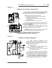
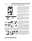
Install ESTOP buttons Do NOT place a jumper across the Emergency Stop terminals. Because the
drive has a ramp to stop capability, this could set up an
UNSAFE
situation. IT IS STRONGLY
RECOMMENDED THAT AN EMERGENCY STOP BUTTON (or an ESTOP relay) BE CONNECTED TO
THE DRIVE! This should be of the MAINTAINED CONTACT TYPE.
The motor thermal must be used to PROPERLY protect the motor!
You can use a "two-wire" control by connecting a contact or switch between terminals 11 and 13 on
TB2. Leave off the RAMP STOP and START buttons. This DOES NOT disable the RAMP STOP function.
The only way to disable the RAMP STOP function is removing the RAMP STOP jumper.
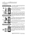
The RAMP STOP function in the analog mode shorts the analog reference input to zero. This causes
the motor to decelerate to zero speed before shut-down.
Note that the JOG function is disabled by the RUN function. If you activate the JOG input while the
RUN mode is in operation, there will be no effect.
The HOLD function zeroes the speed reference to bring the motor to a stop and holds the drive at
zero speed. THE DRIVE IS NOT OFF IN THE HOLD MODE! There is a potential for the motor to run
, so
the appropriate safety precautions should be taken.
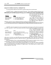
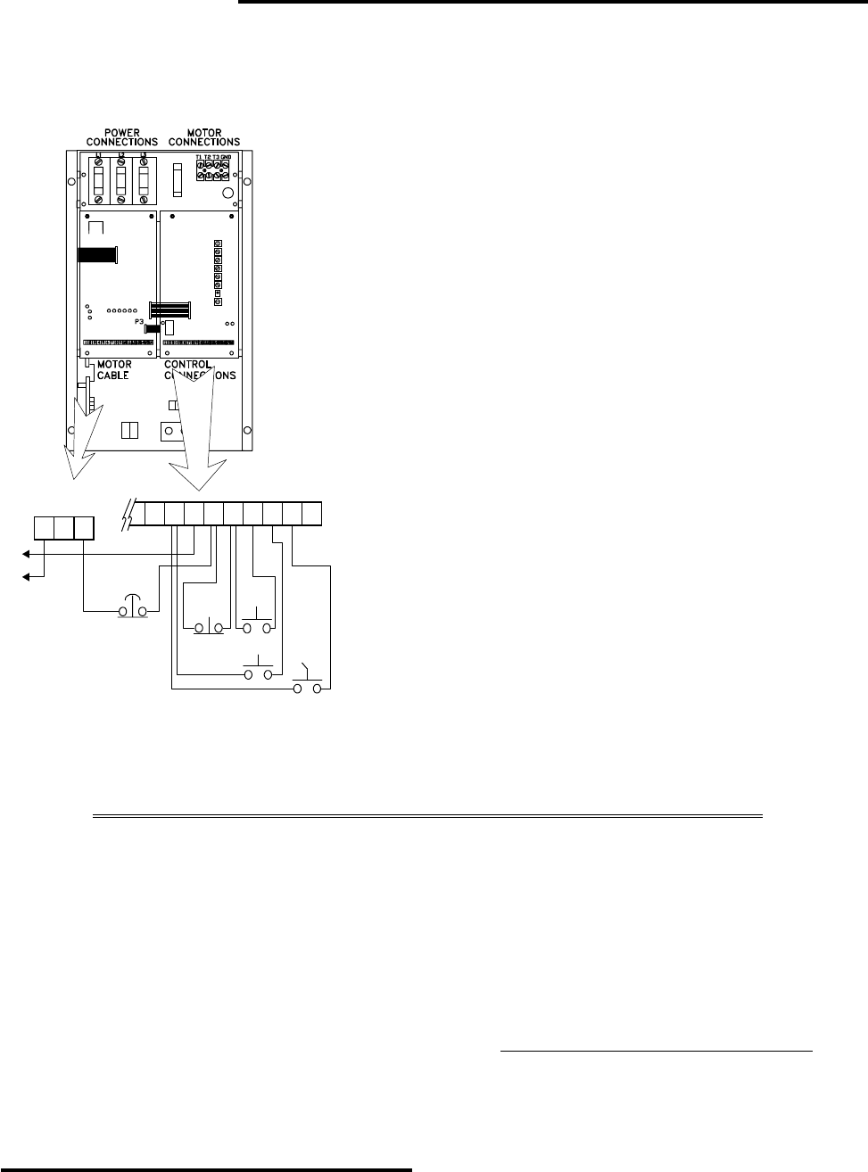
RAMP
STOP
TO
MOTOR
THERMAL
TB2
1615141312111098
START
JOG
RUN HOLD
Bus Loader
Interlock
EMER
STOP
R+ R-
7
321
TB5