


Page
44
Model
1000AR Installation and Operation Manual
6/4/2001 © copyright 1997 by Powertec
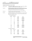
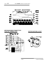
TRANSISTOR MODULE STATIC TEST
Equipment needed: A
D
igital
M
ulti-
M
eter (
DMM
)with a diode scale is preferred. You should have a RED lead
in the positive (+) input and a BLACK lead in the negative (-) input.
Preparation: Different meters give different readings on diode tests. KNOW YOUR METER !! Some
meters read backwards due to battery polarity. Test YOUR meter on a known good diode
bridge before performing tests so that you know how your meter will act.
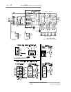
Refer to page 32 for the drive power schematic and semi-conductor diagrams.
Precautions: If the transistor module is to be tested in circuit, make sure power has been off long
enough for the capacitor banks to completely discharge.
Procedure: The procedure is the same for in circuit or out of circuit testing. If a component tests bad
in
circuit, it must be tested again after it is removed because of the possibility of alternate
paths when the component is in circuit.
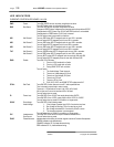
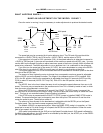
SIX TRANSISTOR MODULE
RED LEAD BLACK LEAD GOOD BAD
P N open short
N P 0.3 to 2.0 short or open
N U 0.3 to 0.7 short or open
N V 0.3 to 0.7 short or open
N W 0.3 to 0.7 short or open
U P 0.3 to 0.7 short or open
V P 0.3 to 0.7 short or open
W P 0.3 to 0.7 short or open
P B1 open short
P B2 open short
P B3 open short
U B4 open short
V B5 open short
W B6 open short
B1 U 0.3 to 500 short or open
B2 V 0.3 to 500 short or open
B3 W 0.3 to 500 short or open
B4 N 0.3 to 500 short or open
B5 N 0.3 to 500 short or open
B6 N 0.3 to 500 short or open
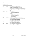
TWO TRANSISTOR MODULE
RED LEAD BLACK LEAD GOOD BAD
C1 E2 open short
E2 C1 0.3 to 2.0 short or open
E2 E1C2 0.3 to 0.7 short or open
E1C2 C1 0.3 to 0.7 short or open
C1 B1 open short
E1C2 B2 open short
B1 E1C2 0.3 to 500 short or open
B2 C2 0.3 to 500 short or open