


Magellan NAV 6500/NAV 651074
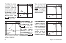
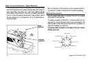
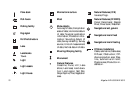
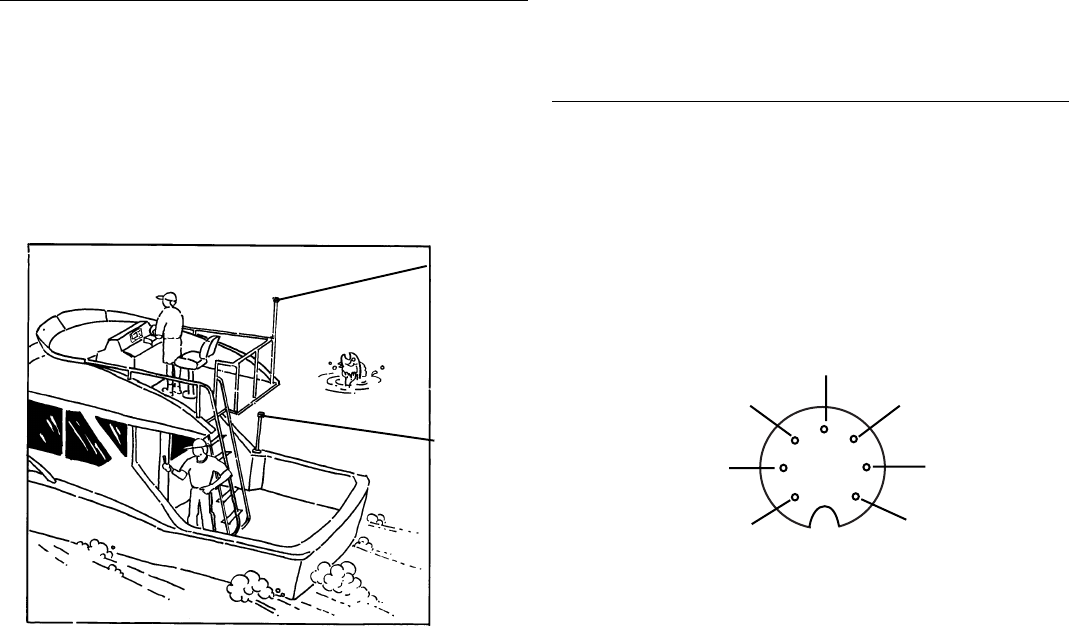
Proper
placement
Improper
placement
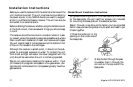
Proper Antenna Installation - Signal Reception
The illustrations show both the proper and improper place-
ment of a fixed antenna on a boat. Physical obstructions (build-
ings, large trees, mountains, etc.) will block satellite signals
from reaching the receiver. If the unit is unable to get a posi-
tion fix, move the receiver antenna so it has a clearer view of
the sky, allowing it to choose from all of the satellites cur-
rently available.
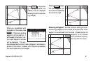
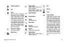
1
2
3
4
5
6
7
NMEA Input -
NMEA Input +
Power +
Shield
NMEA Output +
External Alarm
Differential In +
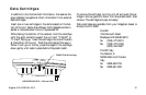
For an illustration of the antenna mounting, see the mount-
ing instruction sheet included with the antenna package.
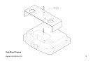
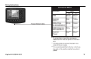
Electrical Connections
Use the power/data cable to connect the unit to a power
source and to data devices.
The receiver accepts 10-35 VDC. It is recommend, but not
required, for a fuse (3A slow blow) to be connected to the
positive lead of the power source. See the wiring diagram to
make the necessary connections.
The power/data connector on the back of the unit has the
following pin-out.