


LX 7007 pro IGC V1.0 Apr.2005
Page 27
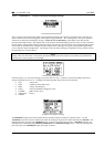
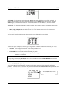
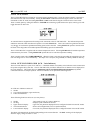
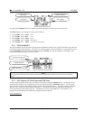
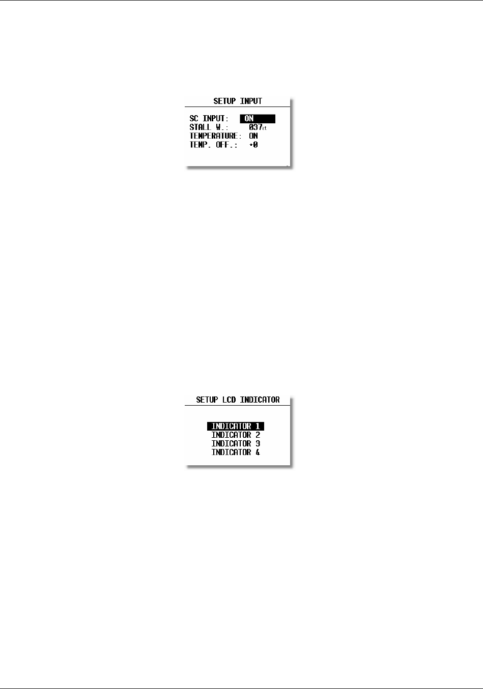
2.1.2.15 SETUP INPUT
The LX 7007 PRO IGC has an input for an external speed command switch. Using the external switch it is possible to
switch between SC and Vario manually. Setting the SC INPUT to ON means that closing the switch will cause the
instrument to enter SC mode, and setting SC INPUT to OFF means that closing the switch will select Vario mode.
There is a third option by setting SC INPUT to TASTER and connecting a push button to the input, each key press will
toggle between SC and Vario.
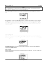
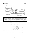
An external alarm to supplement stall warning can be connected to the LX 7007 PRO IGC. The indicated airspeed at
and below which the which the alarm will operate is set under STALL W:. This is also useful in a glider that becomes
very 'draggy' at less than the optimum thermalling speed, such as the LS8. Setting STALL W: speed to coincide with
the onset of the drag bucket will enable optimum thermalling speed to be maintained.
The LX 7007 PRO IGC is supplied with an external temperature sensor. Selecting TEMP. ON will enable temperature
measurement by the sensor. Setting TEMP. OFF permits the user to enter the temperature reading.
There is another input called VARIO PRIORITY. When this input is activated by grounding the appropriate wire, the
unit will change over to Vario immediately. This input wire is set open (not grounded) as a factory default on delivery.
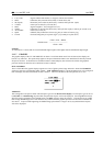
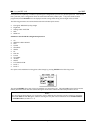
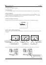
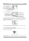
2.1.2.16 SETUP LCD INDICATOR (LCD – Vario Indicator)
The LCD vario indicator is a part of LX 7007 AU. Unlimited number of secondary vario indicators can be connected to
the system using the 485 system bus. The LX 7007 PRO IGC provides 4 different sets of data that can be displayed on
the vario indicators. This means that up to 4 indicators can be set to display different information; any further
connected indicators are simple repeaters. Each LCD indicator is set up from the following menu:
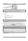
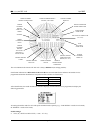
An LCD vario indicator consists of:
• Needle
• Two numerical displays (upper and lower)
• Labels and indicators
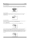
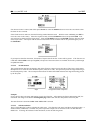
These following functions can be set (see next picture):
• Needle Vario needle (Vario, SC, Netto or Relative)
• SC Ring Displays speed command at all times
• Upper Numeric Display Upper line, the parameter displayed can be configured in both Vario and SC modes
• Vario Mode Indicator Shows current flight mode (vario or speed command)
• Lower Numeric Display Lower line, the parameter displayed can be configured in both Vario and SC modes
The labels will automatically be displayed depending on the current function. The BAT warning will be displayed
when the supply voltage is below 11 volts.