


B KLN 94
Rev. 4, Jan/2003 10599I04.CDL Page 2-9
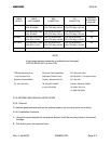
Pin 25; B1
Pin 26; B2
Pin 27; B4
Pin 28; C1
Pin 29; C2
Pin 30; C4
These pins are gray code altitude inputs from an encoding altimeter. If the KLN 94 is paralleled
with another unit such as a transponder, it may be necessary to install isolation diodes between
one or both units and the encoder. The KLN 94 has diodes already installed internally.
Pin 31; GPS DISPLAYED
This pin is used as an input to tell the unit whether an external indicator is connected to the
analog OBS resolver inputs, in which case it will be high. This pin will be grounded if an indicator
is not connected or coupled to the unit.
Pin 32; +TO
Pin 33; +FROM
These outputs function like the outputs from standard navigation converters. For the
specifications on these outputs, refer to Section 1.3 of this manual.
Pin 34; OBS OUT
Pin 35; OBS SIN
Pin 36; OBS COS
Pin 37; OBS RETURN
These pins are the OBS Resolver Interface. This interface is compatible with indicators that are
electrically zeroed (EZ) at 300 degrees and indicators that are omni-ranged zero at 300 degrees.
This interface will operate properly with either “0.85 gain” resolvers or “0.41 gain” resolvers with
no special programming requirements. OBS Resolver Out is a 450 Hz output used to excite the
resolver. The resolver output voltage is then received by the OBS Resolver sine and cosine
inputs.
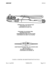
CONFIGURATION MODULE
The configuration module is a separate module from the main rear I/O connector. It is a serial
EEPROM containing at least 32 bytes or 16, 16 (sixteen) 16-bit words.of capacity.